

啥,不懂,手指转的好累。
59680
%7B%22isLastPage%22%3Atrue%2C%22notes%22%3A%5B%5D%2C%22pid%22%3A%22t59680%22%2C%22tid%22%3A%2259680%22%2C%22mainForumsId%22%3A%5B%22165%22%5D%2C%22categoriesId%22%3A%5B%220%22%5D%2C%22tcId%22%3A%5B%5D%7D
%7B%22isEditMode%22%3Afalse%7D
无阀脉冲发动机
Valveless Pulsejet Engines 1.5
-- a historical review of valveless pulsejet designs --
by Bruno Ogorelec
The idea that the simplest engine an enthusiast can make at home is a jet engine will
sound strange to most people -- we perceive jet engines as big complex contraptions pushing
multi-million dollar aircraft through the skies. Yet, this is completely true. In its most basic
form – the valveless pulsejet -- the jet engine can be just an empty metal tube shaped in a
proper way. Everyone able to cut sheet metal and join metal parts can build one in a garage
or basement workshop.
Due to peculiar historical circumstances, this interesting fact has escaped popular
attention. It is not familiar even to enthusiasts of jet propulsion. You are not very likely to see
or hear jet engines roaring in people’s back yards on Sunday afternoon. Few if any people
can be seen flying aircraft powered by jet engines they have built themselves.
This document aims to help change that.
However, it is not a how-to primer. It is an attempt to describe and explain the valveless
pulsejet in principle. It also offers a rough sketch of the amazing variety of layouts the
inventors and developers have tried during the long but obscure history of this device.
My aim is to inspire, rather than teach. My goal is to demonstrate that jet power is
accessible to everyone in a great variety of simple ways. Should you find the inspiration,
plenty of information on the practical steps towards jet power will be available elsewhere.
2
HOW DOES A VALVELESS PULSEJET WORK?
The picture below shows one of the many possible layouts of a valveless pulsejet engine.
It has a chamber with two tubular ports of unequal length and diameter. The port on the right,
curved backwards, is the intake pipe. The bigger, flared one on the left is the exhaust, or
tailpipe. In some other engines, it is the exhaust pipe that is bent into the U-shape, but the
important thing is that the ends of both ports point in the same direction.
When the fuel-air mixture combusts in the chamber, the process generates a great amount
of hot gas very quickly. This happens so fast that it resembles an explosion. The immediate,
explosive rise in internal pressure first compresses the gas inside and then pushes it
forcefully out of the chamber.
Two powerful spurts of hot expanding gas are created – a big one that blows through the
tailpipe and a smaller one blowing through the intake. Leaving the engine, the two jets exert
a pulse of thrust – they push the engine in the opposite direction.
As the gas expands and the combustion chamber empties, the pressure inside the engine
drops. Due to inertia of the moving gas, this drop continues for some time even after the
pressure falls back to atmospheric. The expansion stops only when the momentum of the
gas pulse is completely spent. At that point, there is a partial vacuum inside the engine.
The process now reverses itself. The outside (atmospheric) pressure is now higher than
the pressure inside the engine and fresh air starts rushing into the ends of the two ports. At
the intake side, it quickly passes through the short tube, enters the chamber and mixes with
fuel. The tailpipe, however, is rather longer, so that the incoming air does not even get as far
as the chamber before the engine is refilled and the pressure peaks.
One of the prime reasons for the extra length of the tailpipe is to retain enough of the hot
exhaust gas within the engine at the moment the suction starts. This gas is greatly rarified by
the expansion, but the outside pressure will push it back and increase its density again. Back
in the chamber, this remnant of previous combustion mixes vigorously with the fresh fuel/air
mixture that enters from the other side. The heat of the chamber and the free radicals in the
retained gas will cause ignition and the process will repeat itself.
The spark plug shown on the picture is needed only at start-up. Once the engine fires, the
retained hot gas provides self-ignition and the spark plug becomes unnecessary. Indeed, if
spark ignition is left on, it can interfere with the normal functioning of the engine.
It took me more than 300 words to describe it, but this cycle is actually very brief. In a
small (flying model-sized) pulsejet, it happens more than 250 times a second.
The cycle is similar to that of a conventional flap-valve pulsejet engine, like the big Argus
(which powered the V-1 flying bomb) or the small Dynajet used to power flying models.
There, the rising pressure makes the valve flaps snap shut, leaving only one way for the hot
gas to go -- into the exhaust tube. In the J-shaped and U-shaped valveless engines, gas
spews out of two ports. It does not matter, because they both face in the same direction.
Some valveless pulsejet designers have developed engines that are not bent backwards,
but employ various tricks that work in a similar fashion to valves -- i.e. they allow fresh air to
come in but prevent the hot gas from getting out through the intake. We shall describe some
3
of those tricks at a later point.
You may wonder about the sharp transition from the intake tract into the chamber. It is
necessary to generate strong turbulence in the incoming air, so that it mixes with injected fuel
properly. A gentler, more gradual entry would not generate the necessary swirling of gases.
In addition, turbulence increases the intensity of combustion and the rate of the heat release.
THE BEGINNINGS
The idea of using the elastic properties of air to generate power pulses is very old. The
first pulsejet engines were built in France at the very beginning of the 20th century. They
found only very limited use at the time and were soon forgotten for all practical purposes.
In the 1930s, however, German engineer Paul Schmidt rediscovered the principle by
accident while trying to develop a detonation engine. He built a series of impressive pulsejets
with valves. At roughly the same time and in the same country, engineers at the Argus
engine company were working on a valveless device that used compressed air.
The circumstances were much more propitious now. The world was preparing for a big
war and the war machines were gearing up. The German War Ministry brought Schmidt and
Argus together, which resulted in the development of the first mass produced jet engine. Like
the Schmidt engines, it used valves and natural aspiration, but its mechanisms were greatly
modified by Argus.
Thus, while the opposed sides
in World War II were still trying to
put together their first jet-powered
fighter aircraft in 1944, the
Vergeltungswaffe 1 (or V-1 for
short) was regularly buzzing its
way to England with a 1,870-lb
load of explosives. Its Fieseler
airframe was powered by the
Argus As 109-014 pulsejet engine.
You can see one flying over the
English countryside on the photo
on the right.
The utter simplicity, low cost
and demonstrated effectiveness of
the pulsejet impressed the Allies
so much that they badly wanted to
have something similar. It looked
amazing to everyone that a device
that simple could power a serious
flying machine. Captured
examples of the Argus were
carefully studied and copies built
and tested.
It soon became obvious that the
pulsejet had certain drawbacks
and limitations, but the basic
principle still looked very attractive
and ideas for improvement
abounded. Various uses for the
device were contemplated. Ford Motor Company built a proper assembly line to manufacture
Argus copies. With the end of the war, some of the projects were scuttled, but the Cold War
started soon and the quest for a better pulsejet continued.
Unfortunately, progress was very slow and purely incremental. In the mid 1950s, after a
decade of effort, developers were not that much better off than their wartime German
predecessors. In total contrast, the advances in turbojet design over the same period were
4
tremendous. By that time, turbojet-powered fighters already had the Korean War behind
them. Turbojet strategic bombers were carrying nuclear weapons in their bomb bays and
turbojet airliners were getting ready to earn their money carrying businessmen and the idle
rich from continent to continent.
It was becoming completely clear to everyone that the turbojet was the jet engine of the
future. Engineers were still excited by the promise of the pulsejet, but the reality was not to
be denied. During the 1950s and 1960s, most pulsejet researchers gradually abandoned
their efforts and turned to other things.
THE ADVANTAGES
What originally attracted and excited the researchers and developers most of all about the
pulsejet engine was a peculiar property of pulsating combustion – it can be self-compressing.
In the pulsejet, the fuel-air mixture does not burn steadily, at a constant pressure, as it does in
the other jet engines. It burns intermittently, in a quick succession of explosive pulses. In
each pulse, the gaseous products of combustion are generated too fast to escape from the
combustor at once. This raises the pressure inside the combustor steeply, which increases
combustion efficiency.
The pulsejet is the only jet engine combustor that shows a net pressure gain between the
intake and the exhaust. All the others have to have their highest pressure created at the
intake end of the chamber. From that station on, the pressure falls off. Such a decreasing
pressure gradient serves to prevent the hot gas generated in the combustor from forcing its
way out through the intake. This way, the gas moves only towards the exhaust nozzle in
which pressure is converted to speed.
The great intake pressure is usually provided by some kind of compressor, which is a
complex and expensive bit of machinery and consumes a great amount of power. Much of
the energy generated in the turbojet engine goes to drive a compressor and only the
remainder provides thrust.
The pulsejet is different. Here, the exhaust pressure is higher than the intake pressure.
There is pressure gain across the
combustor, rather than loss. Moreover,
the pulsejet does it without wasting the
power generated by combustion. This
is very important. According to some
rough figures, a 5-percent gain in
combustion pressure achieved by this
method gives about the same
improvement in overall efficiency as the
85-percent gain produced by a
compressor, all other things being
equal. Now, that’s rather impressive.
Personally, I am interested in the
pulsejet for another reason -- because it
brings the jet engine back to the people.
It is a back-to-basics kind of machine,
so simple to be accessible even to
enthusiasts with rudimentary skills and
simple tools. Turbojets and fanjets are
at the opposite end of the complexity
scale. In most cases they employ
inaccessible, cutting-edge technology.
Just look at the collection of
pulsejets on the picture on the right.
They were built by Stephen Bukowsky,
a high-school student, purely out of fun.
5
If I remember it right, the three valveless engines (second, third and fifth from left) each took
him about a couple of days to make. This is just a part of Steve’s collection!
Cost is another advantage. Pulsejets are cheaper than even the simplest piston engines
of comparable output. In contrast, turbojets are frighteningly expensive.
THE DISADVANTAGES
So, given the advantages, why did the pulsejet disappear from view? There are several
reasons.
A big problem is that the gain in efficiency offered by pulsating combustion is not at all
easy to utilize for propulsion. Paradoxically, the central problem here is the same as the
source of the benefit – namely, pulsation. The very means of increasing combustion
efficiency makes it difficult to take advantage of the result.
The real potential for the pulsejet has always been in its use as the combustor for a turbine
engine, rather than as an engine in itself. Its ability to generate pressure gain is greatly
multiplied in a high-pressure environment. Compared to the more usual constant-pressure
combustor, it can either give the same power with much smaller mechanical loss and lower
fuel consumption, or much greater power for the same amount of fuel.
Alas, a turbine demands steady flows to function efficiently. Unsteadiness generates loss.
Also, pulsations are dangerous for the brittle axial turbine blades. Radial turbines are tougher
in that respect, but they are less efficient, especially so with intermittent flow. They are mostly
used to exploit waste heat, as in a turbocharger, rather than as prime movers. Researchers
have toyed with converting pulsations into a steady flow, but most methods proved inefficient.
But, how about simplicity? In a manner of speaking, a pulsejet is what remains when you
remove all the complex and expensive parts from a turbojet and leave only the simple and
cheap combustor that is hidden in the middle.
Well, yes, simplicity is attractive, but it also has its disadvantages. The promise of the
pulsejet on its own, outside a turbojet, is less significant. The pressure gain is still there, but
in the atmospheric pressure environment, without the multiplication offered by the
compressor, it does not amount to very much. The average pressure in the working cycle is
low, the specific power unimpressive and fuel efficiency poor. The power ‘density’ is much
lower too. For the same engine bulk, you get less thrust than with the competing jet engines.
Pushing the pulsejet further down the scale of desirability in the postwar era was the fact
that even with the improvements arrived at in the 1950s and 60s; the pulsations still produced
horrible noise and mad vibration. Pulsejets depending on reed valves were also short-lived
and unreliable. OK, they were cheap, but in the Cold War era that was certainly not a prime
consideration.
Finally, there was little that pulsejets were really good for. For a while, it looked like they
would power small helicopters. Some spectacular-looking prototypes were built, especially in
France. In the end, however, they never made the grade, mostly for aerodynamic reasons.
6
The French briefly used pulsejet power on motor gliders and flying drones, too. Cheap
flying drones and missiles were built in several countries, including the US, Russia and China.
The picture above shows the French Arsenal 501 target drone, powered by a valved engine.
The color picture on the first page of this document shows a Chinese target drone with a
valveless engine.
That was about it. Given the ample defense budgets, most of the real-life applications that
required a jet engine were better satisfied with a turbojet or with rocket power.
Civilian industry did not look upon the pulsejet with any greater kindness. Turbojet
development was intense and engineers had little time for the exotic pulsating things that few
people understood properly anyway. The difficulty of defining the processes inside the
pulsejet mathematically was a major problem for most researchers and engineers. Modeling
the semi-chaotic pulsating combustion was far too much for the computing abilities of the
time. It meant that pulsejet design was unpredictable -- part science and part black art.
Industry tries hard to avoid such tricky propositions.
By the mid-1960s only a few isolated enthusiasts still considered the pulsejet as a potential
aircraft powerplant. The noisy tube was in a blind alley and relegated to the role of model
aircraft engine and such humdrum applications as an efficient combustor for central heating
systems, a power unit for agricultural spray dusters and a blower and shaker for industrial
slurry drying machinery.
CHANGE OF CIRCUMSTANCES
So, why look at pulsejets now? Well, my reason is the change of circumstances.
Sometime in the early 1980s, ultralight fun flying started getting increasingly popular due to
the availability of good, simple and affordable flying platforms – hang gliders and paragliders.
When provided with motor power, these machines offered unprecedented freedom of flight to
anyone interested. In addition, with the fantastic development of modern electronics, a whole
new class of unmanned flying machines appeared, designed as utility platforms for a variety
of telecommunications, surveillance, measuring and sensing devices.
All those new flying machines, whether designed for fun or utility, are powered by piston
engines that drive propellers. Jet engines only appear at the very top end of the price scale –
on machines costing several hundred thousand dollars apiece.
All the piston engines currently used in ultralight flying are relatively heavy and
cumbersome, even in their simplest form. They also require much ancillary equipment, like
reductors, prop shafts, propellers etc. etc. Having all that gear mounted on a lightweight
flying machine almost defeats the original purpose. A simple lightweight pulsejet seems
much more appropriate.
Turbojets, on the other hand, are terribly
expensive – far out of enthusiasts’ reach. Things
are not likely to get much better in the near
future, either. Because of the very high
technological requirements, the cost of turbojet
engines has always remained high. Only the
small turbojets based on old turbocharger parts
are relatively inexpensive, because their most
precious parts are taken off scrapped truck
engines, but even their prices are not pleasant.
In contrast, the humble low-technology
pulsejet is laughingly cheap by any standard.
Besides, in the engine sizes likely to be used
by enthusiasts, the best pulsejets can compete in
performance with the other jet engines,
especially in the power-to-weight stakes.
I am often told that a jet engine will never be good for recreational purposes. Jet
propulsion is really efficient only at relatively high airspeeds, seemingly making it unsuitable
for low-speed devices such as hang gliders. However, maybe a niche for a simple jet engine
7
can be found at the top end of hang-glider performance – possibly with rigid wings.
Also, the rule does not seem to be very strict. For instance, a British Doodlebug harness
powered by a Microjet turbojet engine has been tested with delightful results with a regular
foot-launched hang glider (see the picture).
This bodes well for pulsejets. When equipped with a thrust augmenter, a good pulsejet
can be optimized for speeds much lower than those of other jet engines. It can hardly fail to
perform at least as well as the Microjet in a similar application. In terms of thrust to weight it
is already superior.
Tote up those points and the lightweight, simple, cheap low-speed pulsejet engine
suddenly starts making a lot of sense. Its admittedly high fuel consumption, noise and
vibration need not be of major importance for the applications I have in mind -- or may
perhaps be alleviated or designed out of the concept.
The enormous advances in computing power over the past few decades have made
modeling of pulsating combustion more realistic, too. It is still not easy even for the
supercomputers, but it can now be done. This can cut down development time drastically and
make it much more straightforward.
Finally, our understanding of pulsating combustion has advanced to the point where these
engines can be designed on paper with performance predictability much closer to that of the
other engine types.
It is perhaps time to blow the dust off the old tube.
WHY VALVELESS?
The ordinary pulsejet is already a very simple engine. It is just a piece of tube cut to the
required dimensions, with a few small flaps and a fuel jet at one end. So, one might ask, why
go that one small step further and eliminate the valves?
The prime reason is that the use of flap valves limits the reliability and longevity of the
engine. The valves of the As 109-014 lasted for only about 30 minutes of continuous use.
Given that its role was to destroy itself in the end anyway, this was not a big fault, but today
you might have a flying model that is your pride and joy up in the air, or you may even want to
fly yourself. You really need your engine to last a bit longer.
Admittedly, development has improved the design in many ways and stretched its working
life from minutes into hours, but the fundamental problem remains. In fact, it looks well nigh
insoluble, given that the valves are supposed to satisfy conflicting demands.
In the interest of combustion efficiency, they should not impose their own timing on the
flows. This is very important, as the combustion process is not only intermittent but also
somewhat erratic and highly dependent on feedback. If we want to avoid disturbing the
natural progress of the pulsation as much as possible, the valves must respond to changes of
pressure almost instantaneously. To do that, they have to be as light as possible.
At the same time, however, they have to endure great mechanical stress (bending open
and slamming shut at high-speed) and do it in a high-temperature environment. They have to
be very tough. If something has to be light, yet exposed to great abuse, it either spells short
life or exotic technology. The former is impractical and the latter is expensive.
Finally, there is a question of elegance. I find the idea of a jet engine that is actually just a
cheap empty metal tube without moving parts very appealing. Making the various gases jump
through hoops and produce useful tricks without resorting to any mechanical complexity is a
nifty thing that will be appreciated by all lovers of simplicity and elegance. (I am talking of
elegance in the mathematical sense -- desired result achieved with minimal complication.)
KADENACY OSCILLATION, THERMAL BREATHING AND ACOUSTIC RESONANCE
Before getting into details of actual engine designs, let’s get some important theory out of
8
the way. People who hate theory may skip this part, but my advice is to skip it only if you are
already reasonably familiar with the laws of acoustics and fluid mechanics and aware of how
they pertain to pulsejets. On the other hand, people who like theory should be warned that
the following is a greatly simplified description of very complex mechanisms.
Kadenacy Effect
In the explanation of the working cycle, I described how inertia keeps driving the
expanding gas out of the engine all the way until the pressure in the chamber falls below
atmospheric. The opposite thing happens in the next part of the cycle, when the outside air
pushes its way in to fill the vacuum. The combined momentum of the gases rushing in
through the two opposed ports causes the chamber briefly to be pressurized above
atmospheric before ignition.
There is thus an oscillation of pressure in the engine caused by inertia. The gases
involved in the process (air and gaseous products of combustion) are stretched and
compressed between the inside and outside pressures. In effect, those fluids behave like an
elastic medium, like a piece of rubber. This is called the Kadenacy Effect.
The elastic character of gas is used to store some of the energy created in one
combustion cycle and use it in the next. The energy stored in the pressure differential (partial
vacuum) makes the aspiration (replacement of the burned gas with fresh fuel-air mixture)
possible. Without it, pulsejets would not work.
Some observers have noticed another, additional facet of the process, akin to breathing.
Swiss pulsating combustion wizard Francois H. Reynst called it ‘thermal breathing’ – heating
the gas causes it to expand (and the engine to ‘exhale’) while the cooling of the gas due to
convection of heat to the cooler chamber walls leads to contraction, and the engine ‘inhales’.
Acoustics
Other people studying the process came up with the acoustic explanation of the same
process. They detected acoustic resonance behind the pressure swings.
Namely, the explosion in the chamber generates a pressure wave that strikes the engine
tube and the air within it, making them ‘ring’ like a bell hit by a hammer. The pressure wave
travels up and down the tube. When the wave front reaches an end of the tube, part of it
reflects back. Reflections from opposed ends meet and form the so-called ‘standing wave’.
Everyone who has heard a pulsejet roar knows that it is a sound generator. The fact
needs no amplification – the noise is… well, not just deafening; it is an über-sound that
shakes all things around you seriously. What the establishment of the standing wave means
is that this ‘sound’, just like its lesser brethren, will obey the laws of resonance.
Graphically, the standing wave is best represented by a double sine curve. The same is
true for the pulsejet cycle. The undulations of a single sine curve depict the changes of gas
pressure and gas speed inside a pulsejet engine very well. The doubling of the curve – the
addition of a mirror image, so to say – shows that the places where the pressure and speed
are the highest in one part of the cycle will be the places where they are the lowest in the
opposite part.
The changes of pressure and the changes of gas speed do not coincide. They follow the
same curve but are offset from each other. One trails (or leads) the other by a quarter of the
cycle. If the whole cycle is depicted as a circle – 360 degrees – the speed curve will be offset
from the pressure curve by 90 degrees.
The resonance establishes a pattern of gas pressures and speeds in the engine duct that
is peculiar to the pulsejet and not found in the other jet engines. In some ways it resembles a
2-stroke piston engine resonant exhaust system more than in does a conventional jet engine.
Understanding this pattern is very important, for it helps determine the way the events in the
engine unfold.
When considering a pulsejet design, it is always good to remember that those machines
are governed by a complex interaction of fluid thermodynamics and acoustics.
Elements of Resonance
In acoustic terms, the combustion chamber is the place of the greatest impedance,
meaning that the movement of gas is the most restricted. However, the pressure swings are
the greatest. The chamber is thus a speed node but a pressure antinode.
9
The outer ends of the intake and exhaust ports are the places of the lowest impedance.
They are the places where the gas movement is at the maximum and the speed changes are
the greatest – in other words, they are speed antinodes. The pressure swings are minimal,
so that the port ends are pressure nodes.
The pressure outside the engine is constant (atmospheric). The pressure in the
combustion chamber seesaws regularly above and below atmospheric. The pressure
changes make the gases accelerate through the ports in one direction or another, depending
on whether the pressure in the chamber is above or below atmospheric.
The distance between a node and an antinode is a quarter of the wavelength. This is the
smallest section of a standing wave that a resonating vessel can accommodate. In a
valveless pulsejet, this is the distance between the combustion chamber (pressure antinode)
and the end of the tailpipe (pressure node). This length will determine the fundamental
wavelength of the standing wave that will govern the engine operation.
The distance between the chamber and the end of the intake is rather shorter. It will
accommodate a quarter of a wave of a shorter wavelength. This secondary wavelength must
be an odd harmonic of the fundamental.
Given that a valveless pulsejet is a tube open at both ends, you may wonder at the above
statements. Namely, an open tube is not a quarter-wave resonator. It normally has a
pressure antinode in the center and a node at each end – which comprises half a wavelength.
Nevertheless, it is much closer to reality to look at a valveless engine as two different quarterwave
oscillators mounted back to back than as a single half-wave oscillator. The underlying
half-wave character of the resonance of the entire duct is still there, of course, but its effects
are completely drowned by everything else that is happening inside.
So, the tailpipe length must be an odd multiple of intake pipe lengths for the engine to
work properly. However, please note that we are talking of acoustic length. The required
physical length is somewhat different. It changes with the temperature (which changes the
local speed of sound). Thus, it will not be the same in all parts of the engine. It will not be the
same with the engine cold (e.g. at the startup) and when it is hot, either. This is the source of
much frustration for experimenters and the reason why a new pulsejet invariably requires
some tuning and fiddling to achieve proper working resonance.
Waves and Flows
Both the ‘Kadenacy’ and the ‘acoustic’ approaches to the definition of the pulsejet cycle
are correct. In a roundabout way, both may be considered just different manifestations of the
same thing. However, they are not the same thing. This should not be forgotten.
The classical acoustical phenomena take place at small pressure changes, low gas
velocities and little gas displacement. Sound waves are vibrations -- roughly speaking,
elastic, reversible disturbances in the medium. In pulsejets, we see great pressure variations,
high gas velocities and great gas displacement. The forces involved are stronger than the
elastic forces keeping the molecules of the medium together, meaning that the medium (gas)
is not just made to vibrate, but is irreversibly displaced. It is made to flow.
It is difficult to see the difference between the wave and the flow, but it can be done. A
wave is not a material phenomenon, but an energy phenomenon. It is a moving disturbance
in a force field. That is why it will easily turn any corner, including doubling back 180 degrees.
A fluid flow, which has mass and inertia, will not. So, the two can be made to separate, which
demonstrates that they are in fact two, rather than one.
You can see pressure waves separated from flow in the valveless pulsejet designs that
feature ports with irreversible flows (e.g. an intake that does not also serve as an auxiliary
exhaust). In such ports, pressure waves will move with the flow in one direction and without
the flow in the opposite direction.
To recapitulate, pulsejets follow their own, distinctive, Kadenacy-like cycle of compression
and rarefaction powered by the self-excited explosive combustion process and helped along
by the heat convection pattern. The genesis of the cycle has nothing to do with acoustics and
everything to do with thermodynamics. There is no doubt, however, that the scenario of
events resembles acoustical phenomena very closely. As a consequence, the laws of
acoustics can and do apply. They superimpose themselves over the thermodynamic events
and modify the inflow and outflow of gas, often significantly so.
Because of that, one should watch out for acoustic resonance, knowing that the regular
pressure impulses will inevitably set up standing waves, which will influence the timing and
10
distribution of gas pressure, the speed and intensity of combustion, the speed and intensity of
gas flows etc. The negative influence of resonance must be avoided and – if possible – the
positive influence harnessed to help the engine along.
This is a very complex task and some designs do this better than others. Some have been
brilliant at the task, using a hugely complex concatenation of wave reflections, reversals,
mergers and collisions to boost the efficiency of aspiration and combustion appreciably.
Others have taken only the roughest note of the possibility. I cannot deal with the issue in
great detail because of inadequate knowledge, and will mention it as we go along only in a
superficial manner.
What I am really interested in are the practical results of pulsejet design.
ENGINE DESIGNS
Marconnet
The world may have been shocked into awareness of the pulsejet by the German flying
bomb in the 1940s, but the history of that curious engine goes much further back, to the very
beginning of the 20th century and the efforts of French engineers to develop a gas turbine.
Steam turbine was a fine machine but needed a huge burner, boiler and condenser
apparatus to handle the water vapor cycle. It looked to the innovative French as if hot gas
generated by combustion of fuel might power the turbine wheel just as well as steam did, but
with much less complication, bulk and cost. Pulsating combustion occurred to them because
it provided automatic aspiration. The pulses not only drove hot gas forward to power the
turbine, but also sucked in fresh charge in the condensation part of the cycle. No special
machinery was needed, just a couple of spring-loaded poppet valves.
In 1909, Georges Marconnet went a step further and developed the first pulsating
combustor without valves. It was the grandfather of all valveless pulsejets.
Marconnet figured that a blast inside a chamber would prefer to go through a bigger
exhaust opening, rather than squeezing through a relatively narrow intake. In addition, a
longish diffuser between the intake and the combustion chamber proper would direct the
charge strongly towards the exhaust, the way a trumpet directs sound. He tolerated what hot
gas did escape from the intake.
In their descriptions of the Marconnet engine, F. H. Reynst and J. G. Foa (each in his time
a noted expert on pulsating combustion) agreed that it could not have worked very well, really
requiring forced air at the intake (by a fan or a similar device) if the blowback was to be
avoided. Foa actually called the Marconnet “a bad ramjet” on account of the need for some
ram pressure at the intake. In principle, it does resemble ramjets of a few decades later
rather closely.
To my eyes, the combustion chamber of the Marconnet ‘engine’ lacks a notable means of
creating turbulence in the incoming flow, meaning that the mixing of fuel with air may have
been problematic and the combustion was of a relatively low intensity. Later practitioners of
the art introduced much more pronounced cut-offs between the intake and the combustion
chamber.
While it may not have been very practical either as a jet engine or as a turbine combustor,
the basic idea behind the Marconnet design was good. It just needed development.
11
However, it was not destined to receive it. Even in France, the valveless combustor soon
became just a footnote in history. Outside France, few people were even aware of the idea.
Instead of developing valveless pulsating combustors, most experimenters of Marconnet’s era
concentrated on various layouts incorporating poppet valves.
[A historical note: One of the earliest valve-equipped pulsating combustors to be devised actually
made commercial history. The first gas turbine ever to be marketed commercially was designed by
Hans Holzwarth in 1905 and developed for practical applications by the Swiss Brown Boveri
Corporation. It enjoyed some commercial success between 1908 and 1938, the bulky drum-shaped
devices reportedly operating faultlessly (if not particularly economically) for ages. There are indications
that the Holzwarth combustor, which features intake and exhaust valves, is being re-evaluated for
modern use in low cost turbine engines.]
Schubert
The principle of the valveless pulsating combustor was rediscovered -- by all accounts
independently from Marconnet – by Lt. William Schubert of the US Navy in the early 1940s.
(It was patented in 1944.) His design, called the “resojet” at the time, on account of its
dependence on resonance, is one of the simplest successful valveless designs of all.
The most probable reason for the scant interest in valveless combustors early in the 20th
century was the lack of good means to prevent the wasteful and unpleasant blowback through
the intake. At first sight, the Schubert engine does not look better in that respect than the
Marconnet, just more angular. However, the appearance is deceiving.
First, Schubert’s sharp cutoff at the entrance of the intake port into the chamber provided
strong turbulence for better mixing of fuel and air, as well as more vigorous combustion.
Second, and more interesting, Schubert carefully calculated the geometry of the intake tube
so that the exhaust gas could not exit by the time the pressure inside fell below atmospheric.
The resistance of a tube to the passage of gas depends steeply on the gas temperature.
Thus, the same tube will offer a much greater resistance to outgoing hot gas than to the
incoming cold air. The impedance is inversely proportional to the square root of the gas
temperature. This degree of irreversibility seems to offer the possibility for the cool air
necessary for combustion to get in during the intake part of the cycle, but for the hot gas to
encounter too much resistance to get out during the expansion part.
In practice, it worked less well. For a number of reasons ignored by the simple general
theory, the Schubert engine still displayed a bit of blowback when stationary. It needed to
move forward at some speed (or to have air blown in by a fan) to prevent it. The intake tract
long enough to prevent the blowback completely would choke the air supply too much for
good performance. Nevertheless, the Schubert was a notable step forward from the
Marconnet.
Trick Intakes, Baffles, Serrated Tubes, Convoluted Passages…
After Schubert, a great number of developers tried to come up with other ways of making
the combustor tube irreversible, to have gases moving through the pulsejet in one direction
only. It is not easy to do without a mechanical non-return valve, but the inventors have
nevertheless come up with a variety of tricks supposed to do the job. Some, like Schubert,
introduced ways to make the resistance to the passage of gas unsymmetrical. Others came
up with ways to deflect gases in different directions.
Paul Schmidt and Jean Henri Bertin (among others) tested a number of designs featuring
concave ring baffles in the intake tract, which offered great resistance to back flow but let
fresh air in easily. A simple version of the Bertin baffle intake is pictured below. Fresh air
coming in from the left encounters a series baffles, but flows easily past them. The baffles
12
have increasingly broader openings, forming a diffuser.
In the opposite direction, however, the story is different. Hot exhaust gas will be trying to
expand as it travels forward (towards the left in the picture) and increasing amounts will be
trapped in the pockets between the baffles. Only a relatively small amount will ever be likely
to escape. At least, that was what the designers hoped would happen.
However, all the configurations they had tried produced lower thrust and consumed more
fuel than the equivalent engines with mechanical valves. Most also displayed at least some
blowback, no matter how hard the designer tried to prevent it.
Alas, that is the sad story of almost every valveless pulsejet that employs some kind of
asymmetry of resistance. Such devices never work as well as their designers hope for. They
mostly pitch in only at high gas speeds, meaning that the engine will suffer from at least some
blowback at the beginning of each cycle.
Numerous versions of tubes with similarly serrated walls have been tried, sometimes with
baffles/serrations awaiting exhaust gas on more than one side. The next picture shows a
typical design of that family, from the pen of a man better known for pulsejets with valves.
The problem with most serrated designs is that the return flow is not impeded as much as
their inventors would like because the exhaust gas quickly fills the small concave ‘pockets’ in
the tube sides and forms cushions of pressurized dead air or small trapped vortices, which
offer little resistance to the passing stream. Under some conditions, the flow of gas in one
direction will actually be very similar to the flow in the opposite direction.
Few people will be surprised to hear that the amazingly prolific and spectacularly inventive
researcher of things electrical, Nikola Tesla, also turned his mind to the problem of pulsating
combustion. He wanted to have a good gas generator for his neat smooth-disk rotor turbine
that used the viscosity of the working fluid to transfer energy to a rotating shaft. He
immediately saw that mechanical valves would not offer the simplicity and reliability he had
sought. So, he studied the ways to rectify the gas flow aerodynamically. Eventually he came
up with arguably the best aerodynamic ‘valve’ ever. Its cross section is shown below.
At first glance, it looks like another serrated passage, but if you take a closer look, you can
see that it does not really employ either baffles or dead air pockets. Instead, it just changes
the direction of the gas and turns it upon itself. At each turn, a side blast of gas will push the
main flow towards the side passage that eventually turns backwards. The harder you blow
into that tube, the harder it will resist.
While undoubtedly ingenious, the ‘valvular conduit’, as Tesla called it, never found
practical application to the best of my knowledge. Tesla himself probably did not have time or
13
inclination to pursue its development after applying for patent, being busy with his
experiments in electromagnetism, and the patent was mostly forgotten. As the inventor has
recently become the center of a cult following, his modern disciples have revived the idea. A
few have been built, but I have not been able to find data on their performance.
Escopette
In 1950, dissatisfied with the baffled intake designs, Bertin and his fellow engineers at the
French SNECMA (Societe Nationale d'Etude et de Construction de Moteurs d'Aviation)
corporation simply turned the intake tract backwards. That way, blowback contributed to
thrust. To its designers, the machine looked like one of the old-fashioned musket guns and
they called it Escopette (which is French for musket).
It looks very similar to the picture we used in the introduction. However, the intake does
not curve backwards directly from the combustion chamber. Its first part points straight
ahead. What turns the hot exhaust gases backwards is a separate curved tube mounted at
some distance from the mouth of the intake proper. So, the engine breathes through the gap
between the intake and the 'recuperator', as the designers called the curved tubular deflector.
This neat design deftly exploits the resonance in several different ways.
The functioning of the split intake is subject to some controversy, but simply put, it may be
said that it allows the engine to behave as if its length were variable – long during the
expansion part of the cycle and short during the suction part. During expansion, it treats the
recuperator as a part of the effective length of the engine and uses it to turn the escaping gas
around and increase thrust. In the intake part of the cycle, however, the effective front end is
at the gap between the intake and the recuperator. This reduces the effective length of the
intake and lets the Escopette inhale more easily.
Next, the tailpipe, instead of being just a straight pipe, is in fact a series of steps of
increasing section. Each transition from a straight section into a diffusing section (flaring
cone) represents a point from which the pressure waves traveling up and down the tube will
reflect in the opposite direction and with the opposed sign. A compression (high pressure)
wave passing a step will reflect back as a rarefaction (low pressure) wave and vice versa.
Just glancing at the picture will give you an idea of how many different compression and
rarefaction waves are generated by each blast of the charge in the chamber as it tries to exit
the engine. Remember also that each step of the pipe works at a different temperature from
the preceding or succeeding steps, meaning that the wave will travel at different speeds.
The tracing of the events is not for the faint of heart and is certainly too complex for me to
attempt to describe here. Bertin et al. harnessed all those waves very carefully, tuning them
to produce the maximum possible aid to aspiration. What seems to be happening is that the
engine ‘skips a beat’, so to say. It inhales twice for each expansion cycle, with the second
inhalation topping up the first.
The next trick Bertin employed on the Escopette – for the first time ever in a pulsejet -- was
the utilization of surplus heat in the exhaust stream to increase thrust. The effect is
sometimes called ‘primary thrust augmentation’. It requires some explanation.
The problem starts with the amount of air available for propulsion. Basically, a jet engine
is a device that employs heat to accelerate air. Ambient air is made to pass through the
engine duct and absorb the heat generated inside by combustion. However, air does not flow
through the pulsejet duct the way it does through other jet engines.
14
In a turbojet, a little hot gas pushes along a great quantity of cool air. In pulsejets, a small
amount of air is sucked into the combustion chamber and used for combustion and a slightly
larger amount is sucked back into the exhaust tube between explosions. That is all. There is
no through-flow.
At the same time, the exhaust gas produced by a pulsejet is much hotter than in a turbojet.
Combustion takes place at similar temperatures -- between 2000 and 25000C -- but the
exhaust gas in a turbojet is immediately mixed with a lot of cool air, so that the temperature is
lowered to between 800 and 12000C before it enters the turbine. The main reason is to keep
the turbine from damage. In the pulsejet, which has no moving parts, the exhaust gas does
not need to be cooled. It travels towards the end of the engine at very close to its initial
temperature – two to three times hotter than in a turbojet.
Because there is no through-flow of air, however, there is very little propulsion mass for
this considerable thermal energy to act on. This generates problems. The small mass of
exhaust gas and fresh air is propelled to the maximum speed possible under the
circumstances (the local speed of sound) and no further. The sonic choking of the duct
prevents the gas speed from rising further, despite the fact that there is sufficient energy for
further acceleration. A ‘de Laval’ nozzle would probably push the speed beyond the Mach
barrier, but it does not work at all well with a pulsating flow, so pulsejet designers avoid them.
So, only a small part of the heat liberated by the process of combustion is converted into
useful kinetic energy. Much of the available energy has nowhere to go. At sonic speed, gas
is not capable of absorbing more heat. This generates compression waves that travel up and
down the engine, disrupting the cycle.
In other words, the energy-mass transfer ratio is low and the resulting thrust is lower than it
could be. So, the super-hot exhaust of the pulsejet simply cries out for additional propulsion
mass to heat up and accelerate.
Enter Bertin. He made the exhaust tube on the Escopette progressively larger towards the
end, so that the final section is a veritable bustle. This increased the volume of the exhaust
duct considerably as well as gave the duct a shape that promoted the intake of fresh air
during the suction part of the cycle. The result was an exhaust filled with a large amount of
fresh air, which the engine could use as additional propulsion mass.
Each blast from the combustion chamber pushes the fresh air ‘plug’ mechanically, but the
engine also transfers a lot of its heat to the air, both from the hot tube walls and from the
pushing hot gas. Heating increases static pressure, which increases the speed at which fresh
air is expelled backwards. Much additional thrust is exerted.
The version intended for commercial applications, model 3340, developed static thrust of
about 22 lbs, operating at the frequency of between 90 and 100 Hz. The weight with the
ancillaries was about 11 lbs. At the widest part, the Escopette was only about 4 inches wide,
but the length was a somewhat unwieldy 9 feet plus.
The Escopette is one of the few pulsejets to have carried people aloft. It was extensively
tested on the French Emouchet SA 104 sailplane in various configurations. The first trials
were with a single engine under each wing, but later models carried two and three engines on
each underwing pylon. While the test results were positive – the auxiliary power enabled the
15
pilot to take off and achieve soaring altitude without a tow plane or a winch, it seems that it
was never offered commercially.
Kentfield’s Recuperator
The idea of a recuperator or deflector found several adherents who produced variations on
the theme, some simple and others complex. J. A. C. Kentfield, one of the most recent
scientific researchers in the pulsejet field, tried to make up for the energy lost in turning the
gas flow around by introducing thrust augmentation to the recuperator.
Instead of a simple tube bent backwards, he employed a gently flaring curved cone, which
let fresh air be sucked in by the hot gas stream as extra reaction mass. (This is often called
secondary thrust augmentation, to make it distinct from the kind used in the Escopette. I will
talk about it in more detail in a later chapter.) According to Kentfield, who patented the idea,
the gain more than offset the drag and turbulence losses incurred by the 180-degree turn.
He experimented with variations on the theme a lot. Most recuperators were symmetrical
and used internal vanes to help control the flow and lower the turbulence. Two such designs
are shown on the next two pictures.
The one on the left looks more ambitious. It attempts to harness ram pressure of the
incoming air. Ram pressure would seem to give a welcome boost to the power output at no
16
cost. The J-shaped and U-shaped engines as well as most engines with recuperators up
front must forgo that advantage, as their intake ports are either turned in the wrong direction
or masked by the recuperator structure.
This one has an almost straight path for fresh air from the front intake to the combustion
chamber (see the lower half of the picture). The trick that prevents the exhaust gas from
escaping through the same route may have been borrowed from Tesla, but similar methods
are also used in various other pneumatic flow control devices.
Note the two small airfoil-section vanes in the central passage, right behind the intake
wedge. When the hot exhaust gas is pushed forward by the blast, the part blowing into the
gap between the vanes is divided into two flows, one going upwards and the other going
downwards. Each flow forms a kind of a gas curtain that cuts across the path of the main flow
(see the upper half of the picture). The curtain deflects exhaust gas flow towards the curved
passages that turn the flow around and eventually eject it backwards. As a result, almost all
the exhaust gas that would normally be blown out of the intake port gets deflected and
contributes to the thrust.
According to Kentfield, the simple one on the right outperformed the more complex one on
the left in laboratory testing. I am not surprised. Due to intermittent operation, a pulsejet is
not very good at tapping ram pressure, most of which goes to waste. Providing a straight
path for fresh air is simply not as important as in the other jet engines. A pulsejet will happily
suck air from the side or even from the rear, because it has to accelerate it from standstill
anyway. Its direction matters very little. The only thing that matters is pressure.
Messerschmitt
One of the best practical recuperators I
have seen is the one developed by the
German Messerschmitt company in the early
1970s. The intention of its engineers was to
build an engine that would segue from
pulsating combustion at low speeds at which
ram pressure is poor, to constant combustion
at high speeds, at which the ram pressure is
sufficient to contain combustion. The task
required a deflector that would be efficient in
redirecting the reverse flow coming from the
intake, but would not represent too much of
an obstacle to the entry of fresh air.
I will disregard the ramjet part or the Messerschmitt engine in this explanation, as it is not
the subject of this paper. However, the recuperator is a different story, as it is eminently
usable on ‘ordinary’ pulsejets. It is simple and elegant -- and easy to make even for an
enthusiast of average skill. As you can see, it consists of a simple sharp cone whose rear is
shaped to deflect the blast from behind at the right angle to the engine axis. When stationary,
this did not do much for thrust, but even at relatively gentle forward speed the deflected gas
stream bent backwards, around the engine, helped by the Coanda effect.
For low speeds, Messerschmitt designers provided a nose cowling to help entrain the flow.
As the speed rose, the cowling became less necessary. At a considerable fraction of the
speed of sound, the incoming air stream is so strong that even the deflector is not strictly
necessary anymore, as the hot gas is entrained tightly between the air stream and the outer
engine surface.
Capped Tubes
Gas deflectors need not be ancillaries tacked onto the engine. They can be an integral
part of its structure. For instance, if you put a loose cap over the end of a tube, so that a gap
17
is left between the cap and the tube, you get a kind of deflector that will turn your exhaust
gases backwards. Unlike a separate recuperator, however, this one also serves as the intake
tract. Arguably, this is the simplest valveless pulsejet design of all.
Possibly the most prominent among pulsejet developers to tackle a capped tube design
were none other than the Argus engine company, best known for their reed-valve engine that
powered the V-1 flying bomb. They tested a number of layouts, some of which appear to be
useful only for stationary applications.
The sketch below shows the central part of their valveless engine. The ‘combustion
chamber’ is formed between the bottle shape we know from many other pulsejet designs and
a cap with hemispherical top. Fuel is injected through a nozzle situated on the tip of the cap
and protected from the chamber by a metal grid. The grid functions as a heat sink and
prevents gas from burning at the nozzle itself.
In the first tests, this central core engine was enveloped in a plenum chamber into which
air was forced at pressure by a compressor. Only the exhaust was sticking out. This meant
that the pressure of forced air prevented hot gas from getting out into the plenum chamber
and almost all of it went into the exhaust. (If it were designed to work without the pressurized
shroud, the chamber and the exhaust passage would probably have to be longer than on the
above picture, to provide the necessary resonant properties.)
Argus engineers were apparently delighted with their valveless machine and were about to
develop it for aircraft purposes, but were ordered to halt the work and concentrate on the
valve-equipped engine inspired by Paul Schmidt’s ideas.
One can only wonder how far they would have gone if not rudely interrupted by the
authorities. The next sketch shows the layout they developed to work without forced air. The
outer streamlining is the most obvious difference, but a subtler one is the annular chamber
through which fresh air must pass before it is drawn into the combustion chamber. Curved
arrows on the sketch show the gas paths inside the engine.
It is obvious that the incoming air will swirl in a toroidal vortex that will allow outside layers
of the vortex to detach and slip into the combustion chamber. However, the hot gas exiting
between the chamber and the mantle will also swirl in a vortex – one whose direction of
rotation will be opposite to the direction of the exit from the annular chamber. In addition, the
18
slit through which the annular chamber communicates with the outside is very narrow. It
might let sufficient fresh air in, but will choke when hot gas tries to pass.
The engineers at Argus were almost certainly unaware of the work of F. H. Reynst, whose
pulsating combustors will be described later in this review. Reynst’s machine also utilizes the
special properties of the toroidal vortex. It was first patented in 1933, while Argus developed
its jet almost a decade later. A decade was hardly enough for the relatively obscure Dutch
patent to percolate to German engineers dabbling in jet propulsion. One can only wonder
what influence, if any, Reynst’s idea would have had on engine development had the contact
between the two been made.
As it is, the toroidal vortices must have helped the Argus engine work well, but they are not
central to its operation. The Argus is not essentially different from the bent intake engine
whose sketch – the very first in this paper -- we used to explain the workings of a valveless
pulsejet. The only difference is that a narrow annular gap between the combustion chamber
and the cap is used for intake instead of a bent tube.
Saunders Roe
The next to exploit a similar configuration was C. E. Tharratt, a British researcher working
on pulsejets for the Saunders Roe aircraft company in the early 1950s. I have no idea
whether he was familiar with the Argus layout or not, but the principle he employed is similar.
Here is the simplified longitudinal cross-section of one of his valveless engines.
The ‘cap’ is no longer a simple cap but a mantle that curves inwards and backwards,
following the curvature of the front part of the combustion chamber. Again, the annular gap
between the mantle and the chamber wall serves
as the auxiliary exhaust. During expansion, most
of the hot gas escapes through the exhaust proper,
at the rear end of the engine, but a portion is driven
forward, into this auxiliary exhaust. The device in
the center of the front plate is the fuel injector. Its
fuel jets are disposed radially, injecting fuel at the
right angle to the fresh air flow.
Tharratt apparently cared little for the
effectiveness of the cap as the exhaust, only really
devoting attention to its properties as the intake port. There have been several versions, with
rather different internal arrangements, but they all offered a smooth passage to fresh air
towards the chamber and an indifferently shaped path for the hot gas out.
On the first two diagrams, the engine looks like having a bluff front end, but that is because
it is shown without the streamlined nose. With it in place, the engine looked like this:
Like Hiller and some others, Saunders Roe was trying to develop a small helicopter with
pulsejets at rotor tips. I have seen no records on the success of the project, but it could not
have been great, given that most helicopter history books neglect to mention it even in
19
passing. Of course, it does not necessarily mean that Tharratt’s engine was not good. The
problem here lies with the helicopter concept, rather than the engine. Rotor-tip jet helicopters
are just not a very sound idea, regardless of the kind of engine that is mounted on the rotor.
A detail that makes Tharratt’s designs particularly interesting is the move away from the
chamber-and-tube configuration found in most pulsejets, valved or valveless. It does not
have the traditional ‘tulip’ or ‘bottle’ shape but tapers gently down, somewhat like a baseball
bat or a bowling pin, having no pronounced bulge where the combustion chamber is situated.
Its narrowest point is all the way back, just before the end of the tailpipe.
The tulip shape has been inherited from the petal-valve designs like the popular Dynajet,
and has created a lot of misdirection among enthusiasts. Namely, according to a number of
experts, it does not necessarily have great relevance to what is going on in the engine. The
broad front part is not the combustion chamber and the narrower pipe is not a tailpipe.
In a well-designed pulsejet, Tharratt says, combustion will be going on through most of the
tube interior and there will be no functional difference between the ‘combustion chamber’ and
the ‘tailpipe’. Look at the engines that Paul Schmidt, the father of the modern valved pulsejet,
designed for his own purposes and you will see either a straight, constant-section tube or the
one that broadens (flares) gently towards the exhaust end. The latter layout is shown in the
next picture. The objective is to provide the least possible obstruction to the gas flow and the
propagation of pressure waves.
The reason Dynajet-style pulsejets are broad up front is because the petal valves and air
passages are inefficiently packaged and take up a lot of room. So, to provide an adequate
amount of valve area, the valve head must be disproportionately broad. The tulip ‘waist’ is
nothing but a gentle transition from broad section to narrower.
That may well be true in theory, but in practice, the tulip shape is difficult to do without.
Kadenacy breathing will not take place unless (a) the pressure differential between the
chamber and the ambient is high enough and (b) the differential can be maintained over a
sufficient minimum period. Gas must be pushed forward by sufficient pressure and given
sufficient time to accelerate to a great enough speed. It must gain at least the minimum
momentum necessary for the Kadenacy effect. This requires a certain amount of
confinement.
Generally speaking, the openings through which the combustion chamber is evacuated
and refilled must not be too big, or gas speeds will be too low, the gas momentum will be too
small, and there will be no Kadenacy effect. The engine will not work.
We know that Paul Schmidt achieved exceptional filling ratios of his pulse tubes and quite
probably exceptional rates of flame propagation due to very careful design. That gave him
pressure peaks so high that he could get away with relatively poor confinement of the burning
gases in the tube. Few designers after him have managed to duplicate his results reliably.
Those results simply cannot be taken as a reasonable yardstick.
Tharratt tried to combine the conflicting demands -- providing confinement to the gases,
yet producing the least amount of harmful obstruction -- by having the chamber narrow down
towards the exhaust in a very gentle slope, so that the narrowest part was situated almost at
the very end of the engine. He argued that the shape conformed to the natural shape of
accelerating gas flow. Only the very end of the pipe exhibited a short outward flare, to enable
the fresh air sucked back into the exhaust to enter more easily.
Interestingly, F. Schultz-Grunow, a noted German pulsejet researcher, pronounced this
shape highly unsatisfactory in his landmark comparative study of pulsejet duct shapes. Yet, it
20
obviously worked for Saunders Roe, as more or less the same shape was employed on their
engines with valves, which saw greater use than the valveless ones.
The design remains unusual. No other designer I know of has chosen to emulate it. Yet,
a very basic pulsejet of this kind would be extremely easy for an enthusiast to build. It would
consist just of a kind of a tin can capping the chamber and exhaust pipe of a conventional
pulsejet, like a Bailey, or Atom jet, or any other of a score of small flying-model pulsejets.
Spacers – possibly just simple screws – could hold the cap centered, keep it at a set distance
from the chamber wall and prevent its fore-and-aft movement. An advantage of the design is
the relatively easy altering of the cap placement. Moving the position of the cap slightly
forward or backward will give the builder a way to fine tune the configuration and find the
‘sweet spot’ at which it works best.
The problem will be the same as in any annular design – how to provide the fuel supply
that will allow good mixing. Looking at the Argus engine, perhaps having the propane supply
right at the center of the chamber front plate would work well.
Foa
Joseph G. Foa, another well-known pulsejet researcher, investigated a capped-tube layout
with a very interesting twist. He added the front entry of fresh air. It is shown on the next
diagram.
Such a direct entry reduces the pumping loss and allows the Foa to benefit from ram
pressure (to the extent that a pulsejet can benefit). This is a very elegant flow rectifier and
has reportedly worked well. Perhaps worth noting here is the fact – not mentioned in the
literature that I have seen -- that it is no different in principle from the Escopette ‘recuperator’,
even though its shape looks very different.
Given the simplicity of the layout, I am surprised that something similar has not gained
popularity among amateur enthusiasts. One is truly tempted to consider such an engine as a
DIY project, as the only real difficulty seems to be presented by the semi-toroidal surfaces.
However, as pulsejet enthusiast Mike Kunz has noted, those can be made relatively easily
by cutting sections of bent tube lengthwise to get semicircular-section channels. Such
channel segments (say, four 90-degree ones) are the joined by welding the ends together and
form a nice half-torus. Some people I know have looked at old torque converter casings with
a spark in their eyes, too, but I have not heard of anyone actually using it for this purpose.
[Please note that most diagrams in this book are not at all useful as engineering drawings. Some of
them have been constructed from bits and pieces of information and represent only a rough
representation of what the actual engine layouts were like. Dimensions shown on the sketches are
approximate at the very best. If you build an engine based on any of t
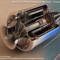

连个图都没有,就算都是简体中文,我也懒得看下去。[s:274]
引用
加载评论中,请稍候...
200字以内,仅用于支线交流,主线讨论请采用回复功能。


无阀脉动喷射引擎1.5
-无阀脉动喷射器设计的历史回顾-
由Bruno Ogorelec的
的想法,爱好者可以在家里做简单的发动机是一台喷气发动机,
对大多数人来说听起来很奇怪-我们认为喷气发动机一样大的复杂的玩意儿
通过天空推多亿美元的飞机。然而,这是完全正确的。在其最基本的
形式-无阀脉动喷射器-喷气发动机可以只是一个空的金属管形在一个
适当的方式。每个人都可以切割金属板材,并加入金属部件可以建立一个在车库
或地下室车间,
由于特殊的历史情况,这个有趣的事实已经逃脱了普遍的
关注。这是不熟悉甚至喷气推进爱好者。你是不是很容易看到
或听到喷气发动机的咆哮,在人们的后院,上周日下午。很少,如果任何人
可以看到由他们已经建立了自己的喷气发动机提供动力的飞机。
本文件旨在帮助改变这种状况,
然而,这是不是一个如何底漆。它试图描述和解释
原则的无阀脉动喷射。
发明者和开发人员已经尝试在此设备的历史长,但晦涩惊人的各种布局,它还提供了一个粗略的草图,
我的目的是启发,而不是教。我的目标是证明喷射动力是
种类繁多,每个人都在简单的方法访问。如果你找到灵感,
大量的喷射动力的切实步骤的信息将可在别处。无阀脉动喷射器的工作如何?下面的图片显示的无阀脉动喷射引擎的许多可能的布局之一。它有一个室两个管状端口不平等的长度和直径。右侧上的端口,向后弯曲,是在吸气管。越大,爆发,一个在左边是排气,或排气管。但在另一些引擎,它被弯曲成U形的排气管,但重要的是,这两个端口的端部的点在同一方向,在室中的燃料-空气混合物燃烧时,该过程将生成大量的热气体速度非常快。这发生如此之快,类似于爆炸。立竿见影,易爆先在内部压力上升压缩气体内,然后把它强行室,创建了两个强大的热膨胀的气体喷-一个大的排气管和一个较小的通过进吹,吹过。离开发动机,两个射流的推力施加一个脉冲-在相反的方向上推发动机,随着气体膨胀和燃烧室清空,在发动机内部的压力下降。由于惯性的运动气体,这种下降持续一段时间后,压力下降到大气。的扩张停止,只有当气体脉冲的势头完全花。在这一点上,有一个在发动机内部的部分真空的方法,现在反转。外面的压力(大气压)现在是在发动机内部的压力高于和新鲜的空气开始冲进的两个端口的端部。在进气侧,迅速 通过短管,进入燃烧室与燃油混合。但是,排气管,而不再是,使进入的空气不甚至据腔室之前,在发动机再填充的压力峰值的额外长度的排气管的首要原因之一是要保留足够的发动机内的热的废气的时刻开始的吸入。此气体大大稀薄的扩展,但外界的压力将其推回,并再次增加其密度。这剩下的以前的燃烧混合室,大力与新鲜的燃料/空气混合物从另一个侧面进入。保留气室和自由基的热量会导致点火的过程中会重演,只需要在启动画面上显示的火花塞。一旦发动机起火,保留的热气体提供自燃和火花塞变得不必要。事实上,如果留在火花点火,它可以影响发动机的正常运作,我花了300多字来形容它,但这个周期其实是非常短暂的。在一个小的(飞行模型大小)脉动喷射器,它发生超过250倍的第二个周期是类似于传统的瓣阀脉动喷射引擎,像大阿格斯()或供电的V-1飞行炸弹使用小Dynajet电源内的模型,在那里,上升的压力使阀瓣突然闭合,只留下一个方式去-到排气管内的热气体。在J形和U形无阀发动机,气体喷出的两个端口。这不要紧,因为他们都面临着在同一个方向。设计师们开发一些无阀脉动喷射引擎不能向后弯曲,但运用各种技巧,以类似的方式对阀门的工作-即他们让新鲜空气进来,但防止热气体通过进气失控。我们将描述一些在稍后的那些招数。3,你可能不知道的急剧转变,从进气腔道进入。这是必要的,进入的空气中产生强湍流,因此,它与喷射的燃料混合,适当地。甲更温和,逐渐进入不会产生必要的气体旋流此外,湍流燃烧和热释放率的强度增加的开端使用的空气的弹性性能,以产生功率脉冲的想法是很老的。第一脉动喷射引擎在法国建造,在开始的20世纪。他们发现,只有使用非常有限的时候,所有的实际目的,并很快被遗忘,然而,在20世纪30年代,德国工程师保罗·施密特重新找回了原则意外而试图开发一个爆震发动机。他建立了一系列令人印象深刻的pulsejets 阀门。在大致相同的时间,在同一个国家,在的阿格斯引擎公司的工程师正在使用压缩空气无阀设备。当时的情况更利于现在。世界正在准备一个大的战争和战争机器摩拳擦掌。德国的战争部带来Schmidt和阿刚一起,导致在第一个大规模生产的喷气发动机的发展。施密特引擎一样,它用阀门和自然吸气,但它的机制,极大地修改通过Argus 因此,在第二次世界大战中,而相对的两侧仍然试图拼凑自己的首个喷气动力的战斗机在1944年,的Vergeltungswaffe 1 (或V-1 )定期嗡嗡英格兰与1,870磅的负载炸药。其Fieseler 机身采用阿格斯109-014脉动喷射发动机,你可以看到在右边的照片上飞过的英国乡村。彻底简单,成本低和证明效力的脉动喷射这么多盟军印象深刻,他们迫切希望有类似的东西。它看起来惊人的给大家,设备简单,动力严重的飞机。捕获的例子阿格斯仔细研究和副本构建和测试,它很快变得明显,脉动喷射器有一定的缺点和局限性,但基本原则仍然显得非常有吸引力的和改进想法比比皆是。拟进行各种各样的用途的设备。福特汽车公司建立了一个正确的组装线,生产阿格斯副本。随着战争结束后,一些项目被破坏了,但冷战开始不久,继续追求一个更好的脉动喷射。不幸的是,进步是非常缓慢的,纯粹的增量。在20世纪50年代中期,经过十年的努力,开发者并不多过得比他们战时的德国前辈。在完全相反,较上年同期涡轮喷气发动机设计的进步是巨大的4 。到那个时候,涡喷发动机为动力的战斗机已的朝鲜战争在他们身后。涡轮喷气发动机战略轰炸机携带核武器炸弹海湾和涡轮喷气客机正准备账面商人和空闲丰富的从大陆到大陆来赚取他们的钱。它变得完全清楚给大家,涡喷未来的喷气发动机。工程师们依然兴奋的脉动喷射器的承诺,但现实情况是不会被拒绝。在20世纪50年代和60年代,大多数的脉动喷射器的研究人员逐渐放弃他们的努力,转向其他的东西。优势最初吸引和兴奋的研究人员和开发人员最重要的所有的脉动喷射引擎的脉动燃烧是一个奇特的属性-它可以是自我压缩脉动喷射器,燃料-空气混合物不燃烧稳定,在一个恒定的压力,因为它在其他喷气发动机。间歇性燃烧,在快速连续爆炸脉冲。在每个脉冲中,气态的燃烧产物产生的速度太快,从燃烧器中逸出的一次。这就提出了在燃烧器内的压力陡峭,从而增加了燃烧效率是唯一的喷气发动机的燃烧器,示出了净增益之间的进气和排气压力的脉动喷射器。所有的人必须有自己的最高压力在进气室。从这个测站上,压力脱落。这种压力梯度减小用于防止从迫使其通过进气在燃烧器中产生的热气体。通过这种方式,气体只朝向排气喷管的压力被转换为速度移动的巨大进气压力通常是由某种类型的压缩机中,这是一个复杂和昂贵的机械位,消耗了大量的功率。涡轮喷气发动机产生的能量去驱动压缩机,只有其余的推力的脉动喷射器是不同的。这里,排气压力高于进气压力,有压力在整个燃烧器的增益,而不是损失。此外,脉动喷射器,它由燃烧产生的功率不浪费。这是非常重要的。根据一些粗略的数字,通过这种方法取得的燃烧压力给5%的涨幅大约在同一改善整体效率,产生85%的收益由压缩机,所有其他的事情都是平等的。现在,这是相当令人印象深刻的,我个人很感兴趣的另一个原因是脉动喷射-因为它带来了喷气发动机的还给人民,这是一个背到基本机种,这么简单的访问,即使爱好者基本的技能和简单的工具。涡轮喷气和fanjets的是在另一端的复杂规模。在大多数情况下,他们采用人迹罕至,尖端技术,只要看看在右图pulsejets 收集。他们纯粹是出于好玩,一所高中的学生,由斯蒂芬·Bukowsky建。5 如果我记得正确,三无阀发动机(第二,第三和左五)各拿他有一对夫妇的天。这仅仅是史蒂夫的集合的一部分成本是另一个优势。Pulsejets甚至比简单的活塞式发动机输出相当便宜。相比之下,涡轮喷气发动机是贵得吓人。缺点因此,给定的优势,为什么脉动喷射器从视图中消失吗?有几个原因,一个大问题是,提供的脉动燃烧效率的增益是不容易利用推进。奇怪的是,这里的核心问题是相同的利益来源-即,脉动。非常手段提高燃烧效率,使得难以利用的结果,在它的使用一直是作为用于涡轮发动机的燃烧器中,而不是作为一个发动机本身的脉动喷射器的真正潜力。它能够产生压力增益大大乘以在高压环境中。更常见的恒压燃烧器相比,可以得到相同的功率更小的机械损失,降低燃料消耗,或更大的功率相同的燃料量。可惜的是,涡轮机要求流量稳定,有效地发挥功能。忽快忽慢产生的损失。此外,脉动是危险的脆性轴流式水轮机叶片。径向涡轮机是强硬的,但他们在这方面的效率较低,尤其是间歇流动。他们大多是用来利用余热,在涡轮增压器中,而不是作为原动机。研究人员玩弄脉动转换成一个稳定的流量,但大多数方法被证明是低效的。但是,如何简单?在某种意义上说,脉动喷射器还有什么,当你删除所有从涡喷发动机的复杂和昂贵的部分,只留下简单和便宜的燃烧室,隐藏在中间。嗯,是的,简单是有吸引力的,但它也有但它的缺点。脉动喷射器对自己的承诺,外涡轮喷气发动机,不太显着。压力增益仍然存在,但在大气压力环境中,如果没有由压缩机提供的乘法运算,它不构成非常多。在工作循环的平均压力是低的,特定的电源不起眼的燃料效率差。功率密度低得多。对于相同的发动机体积,你会得到与竞争喷气发动机推力小于脉动喷射器进一步推下来的规模应该在战后时代是事实,即使与改进,在20世纪50年代和60年代抵达仍在生产的脉动可怕的噪音和振动狂。根据簧片阀Pulsejets也是短命的和不可靠的。OK,他们很便宜,但在冷战时代,肯定不是一个主要的考虑因素。最后,还有一点,pulsejets真的很好。有一段时间,它看起来像他们将电源小型直升机。一些壮观前瞻性的原型建成,尤其是在法国。然而,在最后,他们从来没有档次,多为空气动力学的原因。法国短暂使用机动滑翔机和飞无人机,也脉动喷射器电源。建于几个国家,包括美国,俄罗斯和中国的廉价飞行的无人驾驶飞机和导弹。图为阿森纳的法国501靶机,由阀发动机供电。本文档的第一页上的彩色图片显示了中国人的目标与无阀发动机的无人机,这是它。鉴于充足的国防预算,现实生活中的应用,需要一台喷气发动机更好地满足涡轮喷气发动机或者火箭动力。民用工业脉动喷射后没看任何更大的恩情。涡轮喷气发动机发展是激烈和工程师异国情调的脉动的东西,很少人正确理解反正很少有时间。脉动喷射器内定义的过程的难度,数学是一个重大的问题,大多数研究人员和工程师。半混沌脉动燃烧建模太多时间的计算能力。这意味着脉动喷射器的设计是不可预知的-部分是科学,部分为黑色艺术。产业力图避免这种棘手的命题,到20世纪60年代中期,只有几个孤立的爱好者仍然被认为是作为一个潜在的脉动喷射飞机发动机。嘈杂管无路,退居变化的模型飞机引擎的作用,这样的单调应用中央供热系统作为一种高效燃烧,农用喷雾喷粉器和鼓风机工业浆烘干机械和振动筛的动力装置。情况下,所以,为什么现在看pulsejets?嗯,我的理由是变化的情况下,在20世纪80年代初的某个时候,超轻的乐趣飞开始越来越受欢迎,由于滑翔机和滑翔伞的可用性好,操作简单,经济实惠的飞行平台- 当提供电机功率,这些机器提供前所未有的自由飞行有兴趣的。此外,与梦幻般的现代电子技术的发展,出现一类新的无人飞行机,专为电信,监视,测量和传感设备的各种实用的平台。所有这些新的飞行机器,无论是为了好玩或实用设计,均采用活塞发动机驱动螺旋桨。喷气发动机只出现在非常高端的价格范围- 耗资几十万美元的机器,所有的活塞式发动机目前使用的超轻飞行相对沉重和繁琐,即使在其最简单的形式。他们还需要很多配套设备,减速器,螺旋桨轴,螺旋桨一样,等等,等等,几乎所有齿轮上安装一个轻量级的飞行机器击败的初衷。一个简单的轻量级的脉动喷射器似乎更合适。涡轮喷气发动机,另一方面,是极其昂贵的-远爱好者的接触。事情变得更好,无论是在不久的将来不太可能。由于非常高的技术要求,涡喷发动机的成本一直居高不下。只有基于旧的涡轮增压器零部件的小型涡轮喷气发动机是相对便宜的,因为他们最珍贵的部分采取报废卡车引擎,但甚至他们的价格是不愉快。相比之下,不起眼的技术含量低脉动喷射器是笑着便宜以任何标准来衡量。除了,爱好者可能被用来在发动机尺寸,最好的pulsejets可以竞争与其他喷气发动机性能,尤其是在功率-重量赌注。我经常被告知将永远是好一台喷气发动机作康乐用途。喷气推进器是真正有效的,只有在相对 较高的空速,看似使得它不适合用于低速设备,如滑翔机。然而,也许一个简单的喷气发动机7 利基可以发现在高端滑翔机性能-可能与刚性的翅膀。此外,规则似乎并没有非常严格。举例来说,通过微喷涡轮喷气发动机的一个英国Doodlebug线束供电已经过测试,令人愉快的结果,一个普通的脚推出的悬挂滑翔机(见图片)。这预示着pulsejets的。当配有一个推力增强因子,一个很好的脉动喷射器可以被优化的速度远远低于其他喷气发动机。这种形式也很难失败,至少执行以及微射流在一个类似的应用程序。在推力重量方面,它已经是优于手提包,这些点和轻便,简单,廉价的低速脉动喷射引擎突然开始有很大的意义。其公认的高油耗,噪音和振动不一定是我心目中的应用程序-具有重大意义或可能或许可以减轻或者设计出来的概念。计算能力的巨大进步,在过去几十年里取得了建模脉动燃烧更加逼真,太。它仍然是不容易的,即使在超级计算机,但是它现在可以做到。这可以削减开发时间大幅度使它更直截了当。最后脉动燃烧,我们的理解已经发展到的地步,这些引擎可以设计性能可预测性更接近的其他类型的发动机的纸张上,这也许是时间把尘封已久的旧管无阀为什么?普通脉动喷射引擎已经是一个非常简单的。这仅仅是一块管切割所需的尺寸,与几个小襟翼和燃料喷射的一端。因此,人们可能会问,为什么走一小步进一步消除了阀门?的首要原因是,瓣阀的使用限制的发动机的可靠性和使用寿命。历时仅约30分钟,连续使用的阀门的109-014。鉴于它的作用是自我毁灭的啦,这不是一个大的故障,但今天,你可能有一个飞行模式,是你的骄傲和喜悦在空气中,你甚至还可以自己要飞。你真的需要你的引擎,持续的时间长一点。诚然,发展完善的设计在许多方面捉襟见肘其从几分钟到几个小时的工作寿命,但最根本的问题仍然存在。事实上,它看起来几乎是不溶性的,阀门应该满足相互冲突的需求,在燃烧效率的利益,他们不应该强加自己的时间上的流动。这是非常重要的,因为燃烧过程不仅是间歇性的,但也有些不稳定,高度依赖于反馈。如果我们想尽可能的脉动,以避免干扰的自然进展,阀门必须应对变化的压力几乎瞬间。要做到这一点,他们必须要尽可能轻,在相同的时间,然而,他们不得不忍受巨大的机械应力(弯曲开放,一声关闭在高速),在高温环境下做到这一点。他们必须是非常艰难的。如果东西要轻,还未接触到伟大的虐待,要么法术短寿命或外来技术。前者是不切实际的,而后者则是昂贵的。最后,还有一个问题是优雅。我发现一台喷气发动机的想法,实际上只是一个廉价的空金属管不动,非常有吸引力的部分。各种气体跳火圈,并产生有用的技巧,而不诉诸任何机械复杂,是一个漂亮的东西,将所有热爱简洁和优雅的赞赏。(我说,在数学意义上的优雅-并发症少取得期望的结果。)KADENACY振荡,热的呼吸声共振进入实际的发动机设计的细节之前,让我们得到一些重要的理论出8 的方式。谁恨理论的人可以跳过这一部分,但我的建议是跳过它,只有当你已经相当熟悉声学和流体力学的法律并意识到他们涉及到pulsejets的。另一方面,人们喜欢理论的人应该被警告,以下是一个非常复杂的机制,大大简化描述。Kadenacy 的解释工作周期的影响,我介绍了如何惯性使驾驶膨胀的气体发动机方式,直到腔室中的压力低于大气。与此相反的事情发生在下一周期的一部分,当外面的空气推的方式来填补真空。冲在通过两个相对的端口中的气体将合并的势头简要地使腔室加压点火前的大气压以上,因此,在发动机中的压力振荡引起的转动惯量。的过程中所涉及的气体(空气和燃烧的气态产物)的内部和外部的压力之间的拉伸和压缩。实际上,这些流体的行为像一个弹性介质中,像一块橡皮。这就是所谓的的Kadenacy效应是用来存储在一个燃烧周期中产生的能量,并用它在未来的弹性性质的气体。的压力差(局部的真空)中存储的能量,使得(更换用新鲜的燃料-空气混合物的燃烧后气体)的愿望成为可能。没有它,pulsejets不会工作。一些观察家注意到,额外的小的过程中,就像呼吸。瑞士脉动燃烧精灵弗朗索瓦·Reynst称之为“呼吸热' -加热的气体会发生膨胀(和发动机的气体的冷却,由于对流,热到冷却器的室壁'呼出')而导致的收缩,而发动机的吸入。,声学研究过程中的其他人想出了声解释相同的过程。他们检测到的声共振背后的压力波动,也就是说,在室爆炸产生的压力波撞击发动机管内的空气,使他们'环'就像一个钟锤子击中。的压力波行进向上和向下的管。当波阵面到达该管的端部,它的一部分反射回来。从相对的两端反思的满足,并形成所谓的“驻波”的脉动喷射器的轰鸣声已经听到了每个人都知道,它是一个声音发生器。其实不需要放大-噪声是......嗯,不仅仅是震耳欲聋,它是一个超级的声音,摇动你认真周围的一切事物。建立的驻波手段是什么,这种“声音”,就像它的较小的弟兄,将遵守法律的共振图形,驻波最好的双正弦曲线表示。同样是真实的脉动喷射器循环。一个单一的正弦曲线的起伏描绘脉动喷射发动机内的气体压力和气体速度的变化非常好。加倍的曲线- 另外一个镜像,可以这么说-表明,压力和速度的地方,在一个周期的一部分,是最高的地方,他们是在相反的部分最低。压力变化的压力和气体速度的变化不重合。他们遵循相同的曲线,但彼此抵消。一径(或线索),由一季度的周期。如果整个周期被描绘为一个圆- 360度-速度曲线偏移90度的压力曲线。建立了一个模式的谐振发动机特有的脉动喷射器的管道中气体的压力和速度,并没有发现在喷气发动机。在某些方面,它更类似于一个二冲程活塞式发动机排气系统谐振确实比传统的喷气发动机。了解这种模式是非常重要的,因为它有助于确定引擎中的事件展开。当考虑脉动喷射器设计,始终是良好的,要记住,这些机器都受一个复杂的相互作用的流体热力学和声学元素共振在声学方面,燃烧室的最大阻抗的地方,这意味着气体的运动是最受限制的。但是,压力波动是最大的。因此,腔室的速度节点,但一个压力波腹。9 的进气口和排气口的外端的地方的最低阻抗。它们的气体运动的地方是在最大转速变化 5 -无阀脉动喷射器设计的历史回顾- 由Bruno Ogorelec的爱好者可以在家里做简单的发动机是一台喷气发动机,听起来很奇怪,对大多数人来说-我们认为喷气发动机一样大的复杂的玩意儿推多的想法,数百万美元的飞机,透过天空。然而,这是完全正确的。在其最基本的形式-无阀脉动喷射器-喷气发动机可以只是一个空的金属管形在一个适当的方式。每个人都可以切割金属板材,并加入金属部件可以建立一个在车库或地下室车间,由于特殊的历史情况,这个有趣的事实已经逃脱了普遍的关注。这是不熟悉甚至喷气推进爱好者。你是不是很容易看到或听到喷气发动机的咆哮,在人们的后院,上周日下午。很少,如果任何人可以看到由他们已经建立了自己的喷气发动机提供动力的飞机。本文件旨在帮助改变这种状况,然而,这是不是一个如何底漆。它试图描述和解释原则的无阀脉动喷射。发明者和开发人员已经尝试在此设备的历史长,但晦涩惊人的各种布局,它还提供了一个粗略的草图,我的目的是启发,而不是教。我的目标是证明喷射动力是种类繁多,每个人都在简单的方法访问。如果你找到灵感,大量的喷射动力的切实步骤的信息将可在别处。无阀脉动喷射器的工作如何?下面的图片显示的无阀脉动喷射引擎的许多可能的布局之一。它有一个室两个管状端口不平等的长度和直径。右侧上的端口,向后弯曲,是在吸气管。越大,爆发,一个在左边是排气,或排气管。但在另一些引擎,它被弯曲成U形的排气管,但重要的是,这两个端口的端部的点在同一方向,在室中的燃料-空气混合物燃烧时,该过程将生成大量的热气体速度非常快。这发生如此之快,类似于爆炸。立竿见影,易爆先在内部压力上升压缩气体内,然后把它强行室,创建了两个强大的热膨胀的气体喷-一个大的排气管和一个较小的通过进吹,吹过。离开发动机,两个射流的推力施加一个脉冲-在相反的方向上推发动机,随着气体膨胀和燃烧室清空,在发动机内部的压力下降。由于惯性的运动气体,这种下降持续一段时间后,压力下降到大气。的扩张停止,只有当气体脉冲的势头完全花。在这一点上,有一个在发动机内部的部分真空的方法,现在反转。外面的压力(大气压)现在是在发动机内部的压力高于和新鲜的空气开始冲进的两个端口的端部。在进气侧,迅速 通过短管,进入燃烧室与燃油混合。但是,排气管,而不再是,使进入的空气不甚至据腔室之前,在发动机再填充的压力峰值的额外长度的排气管的首要原因之一是要保留足够的发动机内的热的废气的时刻开始的吸入。此气体大大稀薄的扩展,但外界的压力将其推回,并再次增加其密度。这剩下的以前的燃烧混合室,大力与新鲜的燃料/空气混合物从另一个侧面进入。保留气室和自由基的热量会导致点火的过程中会重演,只需要在启动画面上显示的火花塞。一旦发动机起火,保留的热气体提供自燃和火花塞变得不必要。事实上,如果留在火花点火,它可以影响发动机的正常运作,我花了300多字来形容它,但这个周期其实是非常短暂的。在一个小的(飞行模型大小)脉动喷射器,它发生超过250倍的第二个周期是类似于传统的瓣阀脉动喷射引擎,像大阿格斯()或供电的V-1飞行炸弹使用小Dynajet电源内的模型,在那里,上升的压力使阀瓣突然闭合,只留下一个方式去-到排气管内的热气体。在J形和U形无阀发动机,气体喷出的两个端口。这不要紧,因为他们都面临着在同一个方向。设计师们开发一些无阀脉动喷射引擎不能向后弯曲,但运用各种技巧,以类似的方式对阀门的工作-即他们让新鲜空气进来,但防止热气体通过进气失控。我们将描述一些在稍后的那些招数。3,你可能不知道的急剧转变,从进气腔道进入。这是必要的,进入的空气中产生强湍流,因此,它与喷射的燃料混合,适当地。甲更温和,逐渐进入不会产生必要的气体旋流此外,湍流燃烧和热释放率的强度增加的开端使用的空气的弹性性能,以产生功率脉冲的想法是很老的。第一脉动喷射引擎在法国建造,在开始的20世纪。他们发现,只有使用非常有限的时候,所有的实际目的,并很快被遗忘,然而,在20世纪30年代,德国工程师保罗·施密特重新找回了原则意外而试图开发一个爆震发动机。他建立了一系列令人印象深刻的pulsejets 阀门。在大致相同的时间,在同一个国家,在的阿格斯引擎公司的工程师正在使用压缩空气无阀设备。当时的情况更利于现在。世界正在准备一个大的战争和战争机器摩拳擦掌。德国的战争部带来Schmidt和阿刚一起,导致在第一个大规模生产的喷气发动机的发展。施密特引擎一样,它用阀门和自然吸气,但它的机制,极大地修改通过Argus 因此,在第二次世界大战中,而相对的两侧仍然试图拼凑自己的首个喷气动力的战斗机在1944年,的Vergeltungswaffe 1 (或V-1 )定期嗡嗡英格兰与1,870磅的负载炸药。其Fieseler 机身采用阿格斯109-014脉动喷射发动机,你可以看到在右边的照片上飞过的英国乡村。彻底简单,成本低和证明效力的脉动喷射这么多盟军印象深刻,他们迫切希望有类似的东西。它看起来惊人的给大家,设备简单,动力严重的飞机。捕获的例子阿格斯仔细研究和副本构建和测试,它很快变得明显,脉动喷射器有一定的缺点和局限性,但基本原则仍然显得非常有吸引力的和改进想法比比皆是。拟进行各种各样的用途的设备。福特汽车公司建立了一个正确的组装线,生产阿格斯副本。随着战争结束后,一些项目被破坏了,但冷战开始不久,继续追求一个更好的脉动喷射。不幸的是,进步是非常缓慢的,纯粹的增量。在20世纪50年代中期,经过十年的努力,开发者并不多过得比他们战时的德国前辈。在完全相反,较上年同期涡轮喷气发动机设计的进步是巨大的4 。到那个时候,涡喷发动机为动力的战斗机已的朝鲜战争在他们身后。涡轮喷气发动机战略轰炸机携带核武器炸弹海湾和涡轮喷气客机正准备账面商人和空闲丰富的从大陆到大陆来赚取他们的钱。它变得完全清楚给大家,涡喷未来的喷气发动机。工程师们依然兴奋的脉动喷射器的承诺,但现实情况是不会被拒绝。在20世纪50年代和60年代,大多数的脉动喷射器的研究人员逐渐放弃他们的努力,转向其他的东西。优势最初吸引和兴奋的研究人员和开发人员最重要的所有的脉动喷射引擎的脉动燃烧是一个奇特的属性-它可以是自我压缩脉动喷射器,燃料-空气混合物不燃烧稳定,在一个恒定的压力,因为它在其他喷气发动机。间歇性燃烧,在快速连续爆炸脉冲。在每个脉冲中,气态的燃烧产物产生的速度太快,从燃烧器中逸出的一次。这就提出了在燃烧器内的压力陡峭,从而增加了燃烧效率是唯一的喷气发动机的燃烧器,示出了净增益之间的进气和排气压力的脉动喷射器。所有的人必须有自己的最高压力在进气室。从这个测站上,压力脱落。这种压力梯度减小用于防止从迫使其通过进气在燃烧器中产生的热气体。通过这种方式,气体只朝向排气喷管的压力被转换为速度移动的巨大进气压力通常是由某种类型的压缩机中,这是一个复杂和昂贵的机械位,消耗了大量的功率。涡轮喷气发动机产生的能量去驱动压缩机,只有其余的推力的脉动喷射器是不同的。这里,排气压力高于进气压力,有压力在整个燃烧器的增益,而不是损失。此外,脉动喷射器,它由燃烧产生的功率不浪费。这是非常重要的。根据一些粗略的数字,通过这种方法取得的燃烧压力给5%的涨幅大约在同一改善整体效率,产生85%的收益由压缩机,所有其他的事情都是平等的。现在,这是相当令人印象深刻的,我个人很感兴趣的另一个原因是脉动喷射-因为它带来了喷气发动机的还给人民,这是一个背到基本机种,这么简单的访问,即使爱好者基本的技能和简单的工具。涡轮喷气和fanjets的是在另一端的复杂规模。在大多数情况下,他们采用人迹罕至,尖端技术,只要看看在右图pulsejets 收集。他们纯粹是出于好玩,一所高中的学生,由斯蒂芬·Bukowsky建。5 如果我记得正确,三无阀发动机(第二,第三和左五)各拿他有一对夫妇的天。这仅仅是史蒂夫的集合的一部分成本是另一个优势。Pulsejets甚至比简单的活塞式发动机输出相当便宜。相比之下,涡轮喷气发动机是贵得吓人。缺点因此,给定的优势,为什么脉动喷射器从视图中消失吗?有几个原因,一个大问题是,提供的脉动燃烧效率的增益是不容易利用推进。奇怪的是,这里的核心问题是相同的利益来源-即,脉动。非常手段提高燃烧效率,使得难以利用的结果,在它的使用一直是作为用于涡轮发动机的燃烧器中,而不是作为一个发动机本身的脉动喷射器的真正潜力。它能够产生压力增益大大乘以在高压环境中。更常见的恒压燃烧器相比,可以得到相同的功率更小的机械损失,降低燃料消耗,或更大的功率相同的燃料量。可惜的是,涡轮机要求流量稳定,有效地发挥功能。忽快忽慢产生的损失。此外,脉动是危险的脆性轴流式水轮机叶片。径向涡轮机是强硬的,但他们在这方面的效率较低,尤其是间歇流动。他们大多是用来利用余热,在涡轮增压器中,而不是作为原动机。研究人员玩弄脉动转换成一个稳定的流量,但大多数方法被证明是低效的。但是,如何简单?在某种意义上说,脉动喷射器还有什么,当你删除所有从涡喷发动机的复杂和昂贵的部分,只留下简单和便宜的燃烧室,隐藏在中间。嗯,是的,简单是有吸引力的,但它也有但它的缺点。脉动喷射器对自己的承诺,外涡轮喷气发动机,不太显着。压力增益仍然存在,但在大气压力环境中,如果没有由压缩机提供的乘法运算,它不构成非常多。在工作循环的平均压力是低的,特定的电源不起眼的燃料效率差。功率密度低得多。对于相同的发动机体积,你会得到与竞争喷气发动机推力小于脉动喷射器进一步推下来的规模应该在战后时代是事实,即使与改进,在20世纪50年代和60年代抵达仍在生产的脉动可怕的噪音和振动狂。根据簧片阀Pulsejets也是短命的和不可靠的。OK,他们很便宜,但在冷战时代,肯定不是一个主要的考虑因素。最后,还有一点,pulsejets真的很好。有一段时间,它看起来像他们将电源小型直升机。一些壮观前瞻性的原型建成,尤其是在法国。然而,在最后,他们从来没有档次,多为空气动力学的原因。法国短暂使用机动滑翔机和飞无人机,也脉动喷射器电源。建于几个国家,包括美国,俄罗斯和中国的廉价飞行的无人驾驶飞机和导弹。图为阿森纳的法国501靶机,由阀发动机供电。本文档的第一页上的彩色图片显示了中国人的目标与无阀发动机的无人机,这是它。鉴于充足的国防预算,现实生活中的应用,需要一台喷气发动机更好地满足涡轮喷气发动机或者火箭动力。民用工业脉动喷射后没看任何更大的恩情。涡轮喷气发动机发展是激烈和工程师异国情调的脉动的东西,很少人正确理解反正很少有时间。脉动喷射器内定义的过程的难度,数学是一个重大的问题,大多数研究人员和工程师。半混沌脉动燃烧建模太多时间的计算能力。这意味着脉动喷射器的设计是不可预知的-部分是科学,部分为黑色艺术。产业力图避免这种棘手的命题,到20世纪60年代中期,只有几个孤立的爱好者仍然被认为是作为一个潜在的脉动喷射飞机发动机。嘈杂管无路,退居变化的模型飞机引擎的作用,这样的单调应用中央供热系统作为一种高效燃烧,农用喷雾喷粉器和鼓风机工业浆烘干机械和振动筛的动力装置。情况下,所以,为什么现在看pulsejets?嗯,我的理由是变化的情况下,在20世纪80年代初的某个时候,超轻的乐趣飞开始越来越受欢迎,由于滑翔机和滑翔伞的可用性好,操作简单,经济实惠的飞行平台- 当提供电机功率,这些机器提供前所未有的自由飞行有兴趣的。此外,与梦幻般的现代电子技术的发展,出现一类新的无人飞行机,专为电信,监视,测量和传感设备的各种实用的平台。所有这些新的飞行机器,无论是为了好玩或实用设计,均采用活塞发动机驱动螺旋桨。喷气发动机只出现在非常高端的价格范围- 耗资几十万美元的机器,所有的活塞式发动机目前使用的超轻飞行相对沉重和繁琐,即使在其最简单的形式。他们还需要很多配套设备,减速器,螺旋桨轴,螺旋桨一样,等等,等等,几乎所有齿轮上安装一个轻量级的飞行机器击败的初衷。一个简单的轻量级的脉动喷射器似乎更合适。涡轮喷气发动机,另一方面,是极其昂贵的-远爱好者的接触。事情变得更好,无论是在不久的将来不太可能。由于非常高的技术要求,涡喷发动机的成本一直居高不下。只有基于旧的涡轮增压器零部件的小型涡轮喷气发动机是相对便宜的,因为他们最珍贵的部分采取报废卡车引擎,但甚至他们的价格是不愉快。相比之下,不起眼的技术含量低脉动喷射器是笑着便宜以任何标准来衡量。除了,爱好者可能被用来在发动机尺寸,最好的pulsejets可以竞争与其他喷气发动机性能,尤其是在功率-重量赌注。我经常被告知将永远是好一台喷气发动机作康乐用途。喷气推进器是真正有效的,只有在相对 较高的空速,看似使得它不适合用于低速设备,如滑翔机。然而,也许一个简单的喷气发动机7 利基可以发现在高端滑翔机性能-可能与刚性的翅膀。此外,规则似乎并没有非常严格。举例来说,通过微喷涡轮喷气发动机的一个英国Doodlebug线束供电已经过测试,令人愉快的结果,一个普通的脚推出的悬挂滑翔机(见图片)。这预示着pulsejets的。当配有一个推力增强因子,一个很好的脉动喷射器可以被优化的速度远远低于其他喷气发动机。这种形式也很难失败,至少执行以及微射流在一个类似的应用程序。在推力重量方面,它已经是优于手提包,这些点和轻便,简单,廉价的低速脉动喷射引擎突然开始有很大的意义。其公认的高油耗,噪音和振动不一定是我心目中的应用程序-具有重大意义或可能或许可以减轻或者设计出来的概念。计算能力的巨大进步,在过去几十年里取得了建模脉动燃烧更加逼真,太。它仍然是不容易的,即使在超级计算机,但是它现在可以做到。这可以削减开发时间大幅度使它更直截了当。最后脉动燃烧,我们的理解已经发展到的地步,这些引擎可以设计性能可预测性更接近的其他类型的发动机的纸张上,这也许是时间把尘封已久的旧管无阀为什么?普通脉动喷射引擎已经是一个非常简单的。这仅仅是一块管切割所需的尺寸,与几个小襟翼和燃料喷射的一端。因此,人们可能会问,为什么走一小步进一步消除了阀门?的首要原因是,瓣阀的使用限制的发动机的可靠性和使用寿命。历时仅约30分钟,连续使用的阀门的109-014。鉴于它的作用是自我毁灭的啦,这不是一个大的故障,但今天,你可能有一个飞行模式,是你的骄傲和喜悦在空气中,你甚至还可以自己要飞。你真的需要你的引擎,持续的时间长一点。诚然,发展完善的设计在许多方面捉襟见肘其从几分钟到几个小时的工作寿命,但最根本的问题仍然存在。事实上,它看起来几乎是不溶性的,阀门应该满足相互冲突的需求,在燃烧效率的利益,他们不应该强加自己的时间上的流动。这是非常重要的,因为燃烧过程不仅是间歇性的,但也有些不稳定,高度依赖于反馈。如果我们想尽可能的脉动,以避免干扰的自然进展,阀门必须应对变化的压力几乎瞬间。要做到这一点,他们必须要尽可能轻,在相同的时间,然而,他们不得不忍受巨大的机械应力(弯曲开放,一声关闭在高速),在高温环境下做到这一点。他们必须是非常艰难的。如果东西要轻,还未接触到伟大的虐待,要么法术短寿命或外来技术。前者是不切实际的,而后者则是昂贵的。最后,还有一个问题是优雅。我发现一台喷气发动机的想法,实际上只是一个廉价的空金属管不动,非常有吸引力的部分。各种气体跳火圈,并产生有用的技巧,而不诉诸任何机械复杂,是一个漂亮的东西,将所有热爱简洁和优雅的赞赏。(我说,在数学意义上的优雅-并发症少取得期望的结果。)KADENACY振荡,热的呼吸声共振进入实际的发动机设计的细节之前,让我们得到一些重要的理论出8 的方式。谁恨理论的人可以跳过这一部分,但我的建议是跳过它,只有当你已经相当熟悉声学和流体力学的法律并意识到他们涉及到pulsejets的。另一方面,人们喜欢理论的人应该被警告,以下是一个非常复杂的机制,大大简化描述。Kadenacy 的解释工作周期的影响,我介绍了如何惯性使驾驶膨胀的气体发动机方式,直到腔室中的压力低于大气。与此相反的事情发生在下一周期的一部分,当外面的空气推的方式来填补真空。冲在通过两个相对的端口中的气体将合并的势头简要地使腔室加压点火前的大气压以上,因此,在发动机中的压力振荡引起的转动惯量。的过程中所涉及的气体(空气和燃烧的气态产物)的内部和外部的压力之间的拉伸和压缩。实际上,这些流体的行为像一个弹性介质中,像一块橡皮。这就是所谓的的Kadenacy效应是用来存储在一个燃烧周期中产生的能量,并用它在未来的弹性性质的气体。的压力差(局部的真空)中存储的能量,使得(更换用新鲜的燃料-空气混合物的燃烧后气体)的愿望成为可能。没有它,pulsejets不会工作。一些观察家注意到,额外的小的过程中,就像呼吸。瑞士脉动燃烧精灵弗朗索瓦·Reynst称之为“呼吸热' -加热的气体会发生膨胀(和发动机的气体的冷却,由于对流,热到冷却器的室壁'呼出')而导致的收缩,而发动机的吸入。,声学研究过程中的其他人想出了声解释相同的过程。他们检测到的声共振背后的压力波动,也就是说,在室爆炸产生的压力波撞击发动机管内的空气,使他们'环'就像一个钟锤子击中。的压力波行进向上和向下的管。当波阵面到达该管的端部,它的一部分反射回来。从相对的两端反思的满足,并形成所谓的“驻波”的脉动喷射器的轰鸣声已经听到了每个人都知道,它是一个声音发生器。其实不需要放大-噪声是......嗯,不仅仅是震耳欲聋,它是一个超级的声音,摇动你认真周围的一切事物。建立的驻波手段是什么,这种“声音”,就像它的较小的弟兄,将遵守法律的共振图形,驻波最好的双正弦曲线表示。同样是真实的脉动喷射器循环。一个单一的正弦曲线的起伏描绘脉动喷射发动机内的气体压力和气体速度的变化非常好。加倍的曲线- 另外一个镜像,可以这么说-表明,压力和速度的地方,在一个周期的一部分,是最高的地方,他们是在相反的部分最低。压力变化的压力和气体速度的变化不重合。他们遵循相同的曲线,但彼此抵消。一径(或线索),由一季度的周期。如果整个周期被描绘为一个圆- 360度-速度曲线偏移90度的压力曲线。建立了一个模式的谐振发动机特有的脉动喷射器的管道中气体的压力和速度,并没有发现在喷气发动机。在某些方面,它更类似于一个二冲程活塞式发动机排气系统谐振确实比传统的喷气发动机。了解这种模式是非常重要的,因为它有助于确定引擎中的事件展开。当考虑脉动喷射器设计,始终是良好的,要记住,这些机器都受一个复杂的相互作用的流体热力学和声学元素共振在声学方面,燃烧室的最大阻抗的地方,这意味着气体的运动是最受限制的。但是,压力波动是最大的。因此,腔室的速度节点,但一个压力波腹。9 的进气口和排气口的外端的地方的最低阻抗。它们的气体运动的地方是在最大转速变化 5 -无阀脉动喷射器设计的历史回顾- 由Bruno Ogorelec的爱好者可以在家里做简单的发动机是一台喷气发动机,听起来很奇怪,对大多数人来说-我们认为喷气发动机一样大的复杂的玩意儿推多的想法,数百万美元的飞机,透过天空。然而,这是完全正确的。在其最基本的形式-无阀脉动喷射器-喷气发动机可以只是一个空的金属管形在一个适当的方式。每个人都可以切割金属板材,并加入金属部件可以建立一个在车库或地下室车间,由于特殊的历史情况,这个有趣的事实已经逃脱了普遍的关注。这是不熟悉甚至喷气推进爱好者。你是不是很容易看到或听到喷气发动机的咆哮,在人们的后院,上周日下午。很少,如果任何人可以看到由他们已经建立了自己的喷气发动机提供动力的飞机。本文件旨在帮助改变这种状况,然而,这是不是一个如何底漆。它试图描述和解释原则的无阀脉动喷射。发明者和开发人员已经尝试在此设备的历史长,但晦涩惊人的各种布局,它还提供了一个粗略的草图,我的目的是启发,而不是教。我的目标是证明喷射动力是种类繁多,每个人都在简单的方法访问。如果你找到灵感,大量的喷射动力的切实步骤的信息将可在别处。无阀脉动喷射器的工作如何?下面的图片显示的无阀脉动喷射引擎的许多可能的布局之一。它有一个室两个管状端口不平等的长度和直径。右侧上的端口,向后弯曲,是在吸气管。越大,爆发,一个在左边是排气,或排气管。但在另一些引擎,它被弯曲成U形的排气管,但重要的是,这两个端口的端部的点在同一方向,在室中的燃料-空气混合物燃烧时,该过程将生成大量的热气体速度非常快。这发生如此之快,类似于爆炸。立竿见影,易爆先在内部压力上升压缩气体内,然后把它强行室,创建了两个强大的热膨胀的气体喷-一个大的排气管和一个较小的通过进吹,吹过。离开发动机,两个射流的推力施加一个脉冲-在相反的方向上推发动机,随着气体膨胀和燃烧室清空,在发动机内部的压力下降。由于惯性的运动气体,这种下降持续一段时间后,压力下降到大气。的扩张停止,只有当气体脉冲的势头完全花。在这一点上,有一个在发动机内部的部分真空的方法,现在反转。外面的压力(大气压)现在是在发动机内部的压力高于和新鲜的空气开始冲进的两个端口的端部。在进气侧,迅速 通过短管,进入燃烧室与燃油混合。但是,排气管,而不再是,使进入的空气不甚至据腔室之前,在发动机再填充的压力峰值的额外长度的排气管的首要原因之一是要保留足够的发动机内的热的废气的时刻开始的吸入。此气体大大稀薄的扩展,但外界的压力将其推回,并再次增加其密度。这剩下的以前的燃烧混合室,大力与新鲜的燃料/空气混合物从另一个侧面进入。保留气室和自由基的热量会导致点火的过程中会重演,只需要在启动画面上显示的火花塞。一旦发动机起火,保留的热气体提供自燃和火花塞变得不必要。事实上,如果留在火花点火,它可以影响发动机的正常运作,我花了300多字来形容它,但这个周期其实是非常短暂的。在一个小的(飞行模型大小)脉动喷射器,它发生超过250倍的第二个周期是类似于传统的瓣阀脉动喷射引擎,像大阿格斯()或供电的V-1飞行炸弹使用小Dynajet电源内的模型,在那里,上升的压力使阀瓣突然闭合,只留下一个方式去-到排气管内的热气体。在J形和U形无阀发动机,气体喷出的两个端口。这不要紧,因为他们都面临着在同一个方向。设计师们开发一些无阀脉动喷射引擎不能向后弯曲,但运用各种技巧,以类似的方式对阀门的工作-即他们让新鲜空气进来,但防止热气体通过进气失控。我们将描述一些在稍后的那些招数。3,你可能不知道的急剧转变,从进气腔道进入。这是必要的,进入的空气中产生强湍流,因此,它与喷射的燃料混合,适当地。甲更温和,逐渐进入不会产生必要的气体旋流此外,湍流燃烧和热释放率的强度增加的开端使用的空气的弹性性能,以产生功率脉冲的想法是很老的。第一脉动喷射引擎在法国建造,在开始的20世纪。他们发现,只有使用非常有限的时候,所有的实际目的,并很快被遗忘,然而,在20世纪30年代,德国工程师保罗·施密特重新找回了原则意外而试图开发一个爆震发动机。他建立了一系列令人印象深刻的pulsejets 阀门。在大致相同的时间,在同一个国家,在的阿格斯引擎公司的工程师正在使用压缩空气无阀设备。当时的情况更利于现在。世界正在准备一个大的战争和战争机器摩拳擦掌。德国的战争部带来Schmidt和阿刚一起,导致在第一个大规模生产的喷气发动机的发展。施密特引擎一样,它用阀门和自然吸气,但它的机制,极大地修改通过Argus 因此,在第二次世界大战中,而相对的两侧仍然试图拼凑自己的首个喷气动力的战斗机在1944年,的Vergeltungswaffe 1 (或V-1 )定期嗡嗡英格兰与1,870磅的负载炸药。其Fieseler 机身采用阿格斯109-014脉动喷射发动机,你可以看到在右边的照片上飞过的英国乡村。彻底简单,成本低和证明效力的脉动喷射这么多盟军印象深刻,他们迫切希望有类似的东西。它看起来惊人的给大家,设备简单,动力严重的飞机。捕获的例子阿格斯仔细研究和副本构建和测试,它很快变得明显,脉动喷射器有一定的缺点和局限性,但基本原则仍然显得非常有吸引力的和改进想法比比皆是。拟进行各种各样的用途的设备。福特汽车公司建立了一个正确的组装线,生产阿格斯副本。随着战争结束后,一些项目被破坏了,但冷战开始不久,继续追求一个更好的脉动喷射。不幸的是,进步是非常缓慢的,纯粹的增量。在20世纪50年代中期,经过十年的努力,开发者并不多过得比他们战时的德国前辈。在完全相反,较上年同期涡轮喷气发动机设计的进步是巨大的4 。到那个时候,涡喷发动机为动力的战斗机已的朝鲜战争在他们身后。涡轮喷气发动机战略轰炸机携带核武器炸弹海湾和涡轮喷气客机正准备账面商人和空闲丰富的从大陆到大陆来赚取他们的钱。它变得完全清楚给大家,涡喷未来的喷气发动机。工程师们依然兴奋的脉动喷射器的承诺,但现实情况是不会被拒绝。在20世纪50年代和60年代,大多数的脉动喷射器的研究人员逐渐放弃他们的努力,转向其他的东西。优势最初吸引和兴奋的研究人员和开发人员最重要的所有的脉动喷射引擎的脉动燃烧是一个奇特的属性-它可以是自我压缩脉动喷射器,燃料-空气混合物不燃烧稳定,在一个恒定的压力,因为它在其他喷气发动机。间歇性燃烧,在快速连续爆炸脉冲。在每个脉冲中,气态的燃烧产物产生的速度太快,从燃烧器中逸出的一次。这就提出了在燃烧器内的压力陡峭,从而增加了燃烧效率是唯一的喷气发动机的燃烧器,示出了净增益之间的进气和排气压力的脉动喷射器。所有的人必须有自己的最高压力在进气室。从这个测站上,压力脱落。这种压力梯度减小用于防止从迫使其通过进气在燃烧器中产生的热气体。通过这种方式,气体只朝向排气喷管的压力被转换为速度移动的巨大进气压力通常是由某种类型的压缩机中,这是一个复杂和昂贵的机械位,消耗了大量的功率。涡轮喷气发动机产生的能量去驱动压缩机,只有其余的推力的脉动喷射器是不同的。这里,排气压力高于进气压力,有压力在整个燃烧器的增益,而不是损失。此外,脉动喷射器,它由燃烧产生的功率不浪费。这是非常重要的。根据一些粗略的数字,通过这种方法取得的燃烧压力给5%的涨幅大约在同一改善整体效率,产生85%的收益由压缩机,所有其他的事情都是平等的。现在,这是相当令人印象深刻的,我个人很感兴趣的另一个原因是脉动喷射-因为它带来了喷气发动机的还给人民,这是一个背到基本机种,这么简单的访问,即使爱好者基本的技能和简单的工具。涡轮喷气和fanjets的是在另一端的复杂规模。在大多数情况下,他们采用人迹罕至,尖端技术,只要看看在右图pulsejets 收集。他们纯粹是出于好玩,一所高中的学生,由斯蒂芬·Bukowsky建。5 如果我记得正确,三无阀发动机(第二,第三和左五)各拿他有一对夫妇的天。这仅仅是史蒂夫的集合的一部分成本是另一个优势。Pulsejets甚至比简单的活塞式发动机输出相当便宜。相比之下,涡轮喷气发动机是贵得吓人。缺点因此,给定的优势,为什么脉动喷射器从视图中消失吗?有几个原因,一个大问题是,提供的脉动燃烧效率的增益是不容易利用推进。奇怪的是,这里的核心问题是相同的利益来源-即,脉动。非常手段提高燃烧效率,使得难以利用的结果,在它的使用一直是作为用于涡轮发动机的燃烧器中,而不是作为一个发动机本身的脉动喷射器的真正潜力。它能够产生压力增益大大乘以在高压环境中。更常见的恒压燃烧器相比,可以得到相同的功率更小的机械损失,降低燃料消耗,或更大的功率相同的燃料量。可惜的是,涡轮机要求流量稳定,有效地发挥功能。忽快忽慢产生的损失。此外,脉动是危险的脆性轴流式水轮机叶片。径向涡轮机是强硬的,但他们在这方面的效率较低,尤其是间歇流动。他们大多是用来利用余热,在涡轮增压器中,而不是作为原动机。研究人员玩弄脉动转换成一个稳定的流量,但大多数方法被证明是低效的。但是,如何简单?在某种意义上说,脉动喷射器还有什么,当你删除所有从涡喷发动机的复杂和昂贵的部分,只留下简单和便宜的燃烧室,隐藏在中间。嗯,是的,简单是有吸引力的,但它也有但它的缺点。脉动喷射器对自己的承诺,外涡轮喷气发动机,不太显着。压力增益仍然存在,但在大气压力环境中,如果没有由压缩机提供的乘法运算,它不构成非常多。在工作循环的平均压力是低的,特定的电源不起眼的燃料效率差。功率密度低得多。对于相同的发动机体积,你会得到与竞争喷气发动机推力小于脉动喷射器进一步推下来的规模应该在战后时代是事实,即使与改进,在20世纪50年代和60年代抵达仍在生产的脉动可怕的噪音和振动狂。根据簧片阀Pulsejets也是短命的和不可靠的。OK,他们很便宜,但在冷战时代,肯定不是一个主要的考虑因素。最后,还有一点,pulsejets真的很好。有一段时间,它看起来像他们将电源小型直升机。一些壮观前瞻性的原型建成,尤其是在法国。然而,在最后,他们从来没有档次,多为空气动力学的原因。法国短暂使用机动滑翔机和飞无人机,也脉动喷射器电源。建于几个国家,包括美国,俄罗斯和中国的廉价飞行的无人驾驶飞机和导弹。图为阿森纳的法国501靶机,由阀发动机供电。本文档的第一页上的彩色图片显示了中国人的目标与无阀发动机的无人机,这是它。鉴于充足的国防预算,现实生活中的应用,需要一台喷气发动机更好地满足涡轮喷气发动机或者火箭动力。民用工业脉动喷射后没看任何更大的恩情。涡轮喷气发动机发展是激烈和工程师异国情调的脉动的东西,很少人正确理解反正很少有时间。脉动喷射器内定义的过程的难度,数学是一个重大的问题,大多数研究人员和工程师。半混沌脉动燃烧建模太多时间的计算能力。这意味着脉动喷射器的设计是不可预知的-部分是科学,部分为黑色艺术。产业力图避免这种棘手的命题,到20世纪60年代中期,只有几个孤立的爱好者仍然被认为是作为一个潜在的脉动喷射飞机发动机。嘈杂管无路,退居变化的模型飞机引擎的作用,这样的单调应用中央供热系统作为一种高效燃烧,农用喷雾喷粉器和鼓风机工业浆烘干机械和振动筛的动力装置。情况下,所以,为什么现在看pulsejets?嗯,我的理由是变化的情况下,在20世纪80年代初的某个时候,超轻的乐趣飞开始越来越受欢迎,由于滑翔机和滑翔伞的可用性好,操作简单,经济实惠的飞行平台- 当提供电机功率,这些机器提供前所未有的自由飞行有兴趣的。此外,与梦幻般的现代电子技术的发展,出现一类新的无人飞行机,专为电信,监视,测量和传感设备的各种实用的平台。所有这些新的飞行机器,无论是为了好玩或实用设计,均采用活塞发动机驱动螺旋桨。喷气发动机只出现在非常高端的价格范围- 耗资几十万美元的机器,所有的活塞式发动机目前使用的超轻飞行相对沉重和繁琐,即使在其最简单的形式。他们还需要很多配套设备,减速器,螺旋桨轴,螺旋桨一样,等等,等等,几乎所有齿轮上安装一个轻量级的飞行机器击败的初衷。一个简单的轻量级的脉动喷射器似乎更合适。涡轮喷气发动机,另一方面,是极其昂贵的-远爱好者的接触。事情变得更好,无论是在不久的将来不太可能。由于非常高的技术要求,涡喷发动机的成本一直居高不下。只有基于旧的涡轮增压器零部件的小型涡轮喷气发动机是相对便宜的,因为他们最珍贵的部分采取报废卡车引擎,但甚至他们的价格是不愉快。相比之下,不起眼的技术含量低脉动喷射器是笑着便宜以任何标准来衡量。除了,爱好者可能被用来在发动机尺寸,最好的pulsejets可以竞争与其他喷气发动机性能,尤其是在功率-重量赌注。我经常被告知将永远是好一台喷气发动机作康乐用途。喷气推进器是真正有效的,只有在相对 较高的空速,看似使得它不适合用于低速设备,如滑翔机。然而,也许一个简单的喷气发动机7 利基可以发现在高端滑翔机性能-可能与刚性的翅膀。此外,规则似乎并没有非常严格。举例来说,通过微喷涡轮喷气发动机的一个英国Doodlebug线束供电已经过测试,令人愉快的结果,一个普通的脚推出的悬挂滑翔机(见图片)。这预示着pulsejets的。当配有一个推力增强因子,一个很好的脉动喷射器可以被优化的速度远远低于其他喷气发动机。这种形式也很难失败,至少执行以及微射流在一个类似的应用程序。在推力重量方面,它已经是优于手提包,这些点和轻便,简单,廉价的低速脉动喷射引擎突然开始有很大的意义。其公认的高油耗,噪音和振动不一定是我心目中的应用程序-具有重大意义或可能或许可以减轻或者设计出来的概念。计算能力的巨大进步,在过去几十年里取得了建模脉动燃烧更加逼真,太。它仍然是不容易的,即使在超级计算机,但是它现在可以做到。这可以削减开发时间大幅度使它更直截了当。最后脉动燃烧,我们的理解已经发展到的地步,这些引擎可以设计性能可预测性更接近的其他类型的发动机的纸张上,这也许是时间把尘封已久的旧管无阀为什么?普通脉动喷射引擎已经是一个非常简单的。这仅仅是一块管切割所需的尺寸,与几个小襟翼和燃料喷射的一端。因此,人们可能会问,为什么走一小步进一步消除了阀门?的首要原因是,瓣阀的使用限制的发动机的可靠性和使用寿命。历时仅约30分钟,连续使用的阀门的109-014。鉴于它的作用是自我毁灭的啦,这不是一个大的故障,但今天,你可能有一个飞行模式,是你的骄傲和喜悦在空气中,你甚至还可以自己要飞。你真的需要你的引擎,持续的时间长一点。诚然,发展完善的设计在许多方面捉襟见肘其从几分钟到几个小时的工作寿命,但最根本的问题仍然存在。事实上,它看起来几乎是不溶性的,阀门应该满足相互冲突的需求,在燃烧效率的利益,他们不应该强加自己的时间上的流动。这是非常重要的,因为燃烧过程不仅是间歇性的,但也有些不稳定,高度依赖于反馈。如果我们想尽可能的脉动,以避免干扰的自然进展,阀门必须应对变化的压力几乎瞬间。要做到这一点,他们必须要尽可能轻,在相同的时间,然而,他们不得不忍受巨大的机械应力(弯曲开放,一声关闭在高速),在高温环境下做到这一点。他们必须是非常艰难的。如果东西要轻,还未接触到伟大的虐待,要么法术短寿命或外来技术。前者是不切实际的,而后者则是昂贵的。最后,还有一个问题是优雅。我发现一台喷气发动机的想法,实际上只是一个廉价的空金属管不动,非常有吸引力的部分。各种气体跳火圈,并产生有用的技巧,而不诉诸任何机械复杂,是一个漂亮的东西,将所有热爱简洁和优雅的赞赏。(我说,在数学意义上的优雅-并发症少取得期望的结果。)KADENACY振荡,热的呼吸声共振进入实际的发动机设计的细节之前,让我们得到一些重要的理论出8 的方式。谁恨理论的人可以跳过这一部分,但我的建议是跳过它,只有当你已经相当熟悉声学和流体力学的法律并意识到他们涉及到pulsejets的。另一方面,人们喜欢理论的人应该被警告,以下是一个非常复杂的机制,大大简化描述。Kadenacy 的解释工作周期的影响,我介绍了如何惯性使驾驶膨胀的气体发动机方式,直到腔室中的压力低于大气。与此相反的事情发生在下一周期的一部分,当外面的空气推的方式来填补真空。冲在通过两个相对的端口中的气体将合并的势头简要地使腔室加压点火前的大气压以上,因此,在发动机中的压力振荡引起的转动惯量。的过程中所涉及的气体(空气和燃烧的气态产物)的内部和外部的压力之间的拉伸和压缩。实际上,这些流体的行为像一个弹性介质中,像一块橡皮。这就是所谓的的Kadenacy效应是用来存储在一个燃烧周期中产生的能量,并用它在未来的弹性性质的气体。的压力差(局部的真空)中存储的能量,使得(更换用新鲜的燃料-空气混合物的燃烧后气体)的愿望成为可能。没有它,pulsejets不会工作。一些观察家注意到,额外的小的过程中,就像呼吸。瑞士脉动燃烧精灵弗朗索瓦·Reynst称之为“呼吸热' -加热的气体会发生膨胀(和发动机的气体的冷却,由于对流,热到冷却器的室壁'呼出')而导致的收缩,而发动机的吸入。,声学研究过程中的其他人想出了声解释相同的过程。他们检测到的声共振背后的压力波动,也就是说,在室爆炸产生的压力波撞击发动机管内的空气,使他们'环'就像一个钟锤子击中。的压力波行进向上和向下的管。当波阵面到达该管的端部,它的一部分反射回来。从相对的两端反思的满足,并形成所谓的“驻波”的脉动喷射器的轰鸣声已经听到了每个人都知道,它是一个声音发生器。其实不需要放大-噪声是......嗯,不仅仅是震耳欲聋,它是一个超级的声音,摇动你认真周围的一切事物。建立的驻波手段是什么,这种“声音”,就像它的较小的弟兄,将遵守法律的共振图形,驻波最好的双正弦曲线表示。同样是真实的脉动喷射器循环。一个单一的正弦曲线的起伏描绘脉动喷射发动机内的气体压力和气体速度的变化非常好。加倍的曲线- 另外一个镜像,可以这么说-表明,压力和速度的地方,在一个周期的一部分,是最高的地方,他们是在相反的部分最低。压力变化的压力和气体速度的变化不重合。他们遵循相同的曲线,但彼此抵消。一径(或线索),由一季度的周期。如果整个周期被描绘为一个圆- 360度-速度曲线偏移90度的压力曲线。建立了一个模式的谐振发动机特有的脉动喷射器的管道中气体的压力和速度,并没有发现在喷气发动机。在某些方面,它更类似于一个二冲程活塞式发动机排气系统谐振确实比传统的喷气发动机。了解这种模式是非常重要的,因为它有助于确定引擎中的事件展开。当考虑脉动喷射器设计,始终是良好的,要记住,这些机器都受一个复杂的相互作用的流体热力学和声学元素共振在声学方面,燃烧室的最大阻抗的地方,这意味着气体的运动是最受限制的。但是,压力波动是最大的。因此,腔室的速度节点,但一个压力波腹。9 的进气口和排气口的外端的地方的最低阻抗。它们的气体运动的地方是在最大转速变化 在其最基本的形式-无阀脉动喷射器-喷气发动机可以只是一个空的金属管形在一个适当的方式。每个人都可以切割金属板材,并加入金属部件可以建立一个在车库或地下室车间,由于特殊的历史情况,这个有趣的事实已经逃脱了普遍的关注。这是不熟悉甚至喷气推进爱好者。你是不是很容易看到或听到喷气发动机的咆哮,在人们的后院,上周日下午。很少,如果任何人可以看到由他们已经建立了自己的喷气发动机提供动力的飞机。本文件旨在帮助改变这种状况,然而,这是不是一个如何底漆。它试图描述和解释原则的无阀脉动喷射。发明者和开发人员已经尝试在此设备的历史长,但晦涩惊人的各种布局,它还提供了一个粗略的草图,我的目的是启发,而不是教。我的目标是证明喷射动力是种类繁多,每个人都在简单的方法访问。如果你找到灵感,大量的喷射动力的切实步骤的信息将可在别处。无阀脉动喷射器的工作如何?下面的图片显示的无阀脉动喷射引擎的许多可能的布局之一。它有一个室两个管状端口不平等的长度和直径。右侧上的端口,向后弯曲,是在吸气管。越大,爆发,一个在左边是排气,或排气管。但在另一些引擎,它被弯曲成U形的排气管,但重要的是,这两个端口的端部的点在同一方向,在室中的燃料-空气混合物燃烧时,该过程将生成大量的热气体速度非常快。这发生如此之快,类似于爆炸。立竿见影,易爆先在内部压力上升压缩气体内,然后把它强行室,创建了两个强大的热膨胀的气体喷-一个大的排气管和一个较小的通过进吹,吹过。离开发动机,两个射流的推力施加一个脉冲-在相反的方向上推发动机,随着气体膨胀和燃烧室清空,在发动机内部的压力下降。由于惯性的运动气体,这种下降持续一段时间后,压力下降到大气。的扩张停止,只有当气体脉冲的势头完全花。在这一点上,有一个在发动机内部的部分真空的方法,现在反转。外面的压力(大气压)现在是在发动机内部的压力高于和新鲜的空气开始冲进的两个端口的端部。在进气侧,迅速 通过短管,进入燃烧室与燃油混合。但是,排气管,而不再是,使进入的空气不甚至据腔室之前,在发动机再填充的压力峰值的额外长度的排气管的首要原因之一是要保留足够的发动机内的热的废气的时刻开始的吸入。此气体大大稀薄的扩展,但外界的压力将其推回,并再次增加其密度。这剩下的以前的燃烧混合室,大力与新鲜的燃料/空气混合物从另一个侧面进入。保留气室和自由基的热量会导致点火的过程中会重演,只需要在启动画面上显示的火花塞。一旦发动机起火,保留的热气体提供自燃和火花塞变得不必要。事实上,如果留在火花点火,它可以影响发动机的正常运作,我花了300多字来形容它,但这个周期其实是非常短暂的。在一个小的(飞行模型大小)脉动喷射器,它发生超过250倍的第二个周期是类似于传统的瓣阀脉动喷射引擎,像大阿格斯()或供电的V-1飞行炸弹使用小Dynajet电源内的模型,在那里,上升的压力使阀瓣突然闭合,只留下一个方式去-到排气管内的热气体。在J形和U形无阀发动机,气体喷出的两个端口。这不要紧,因为他们都面临着在同一个方向。设计师们开发一些无阀脉动喷射引擎不能向后弯曲,但运用各种技巧,以类似的方式对阀门的工作-即他们让新鲜空气进来,但防止热气体通过进气失控。我们将描述一些在稍后的那些招数。3,你可能不知道的急剧转变,从进气腔道进入。这是必要的,进入的空气中产生强湍流,因此,它与喷射的燃料混合,适当地。甲更温和,逐渐进入不会产生必要的气体旋流此外,湍流燃烧和热释放率的强度增加的开端使用的空气的弹性性能,以产生功率脉冲的想法是很老的。第一脉动喷射引擎在法国建造,在开始的20世纪。他们发现,只有使用非常有限的时候,所有的实际目的,并很快被遗忘,然而,在20世纪30年代,德国工程师保罗·施密特重新找回了原则意外而试图开发一个爆震发动机。他建立了一系列令人印象深刻的pulsejets 阀门。在大致相同的时间,在同一个国家,在的阿格斯引擎公司的工程师正在使用压缩空气无阀设备。当时的情况更利于现在。世界正在准备一个大的战争和战争机器摩拳擦掌。德国的战争部带来Schmidt和阿刚一起,导致在第一个大规模生产的喷气发动机的发展。施密特引擎一样,它用阀门和自然吸气,但它的机制,极大地修改通过Argus 因此,在第二次世界大战中,而相对的两侧仍然试图拼凑自己的首个喷气动力的战斗机在1944年,的Vergeltungswaffe 1 (或V-1 )定期嗡嗡英格兰与1,870磅的负载炸药。其Fieseler 机身采用阿格斯109-014脉动喷射发动机,你可以看到在右边的照片上飞过的英国乡村。彻底简单,成本低和证明效力的脉动喷射这么多盟军印象深刻,他们迫切希望有类似的东西。它看起来惊人的给大家,设备简单,动力严重的飞机。捕获的例子阿格斯仔细研究和副本构建和测试,它很快变得明显,脉动喷射器有一定的缺点和局限性,但基本原则仍然显得非常有吸引力的和改进想法比比皆是。拟进行各种各样的用途的设备。福特汽车公司建立了一个正确的组装线,生产阿格斯副本。随着战争结束后,一些项目被破坏了,但冷战开始不久,继续追求一个更好的脉动喷射。不幸的是,进步是非常缓慢的,纯粹的增量。在20世纪50年代中期,经过十年的努力,开发者并不多过得比他们战时的德国前辈。在完全相反,较上年同期涡轮喷气发动机设计的进步是巨大的4 。到那个时候,涡喷发动机为动力的战斗机已的朝鲜战争在他们身后。涡轮喷气发动机战略轰炸机携带核武器炸弹海湾和涡轮喷气客机正准备账面商人和空闲丰富的从大陆到大陆来赚取他们的钱。它变得完全清楚给大家,涡喷未来的喷气发动机。工程师们依然兴奋的脉动喷射器的承诺,但现实情况是不会被拒绝。在20世纪50年代和60年代,大多数的脉动喷射器的研究人员逐渐放弃他们的努力,转向其他的东西。优势最初吸引和兴奋的研究人员和开发人员最重要的所有的脉动喷射引擎的脉动燃烧是一个奇特的属性-它可以是自我压缩脉动喷射器,燃料-空气混合物不燃烧稳定,在一个恒定的压力,因为它在其他喷气发动机。间歇性燃烧,在快速连续爆炸脉冲。在每个脉冲中,气态的燃烧产物产生的速度太快,从燃烧器中逸出的一次。这就提出了在燃烧器内的压力陡峭,从而增加了燃烧效率是唯一的喷气发动机的燃烧器,示出了净增益之间的进气和排气压力的脉动喷射器。所有的人必须有自己的最高压力在进气室。从这个测站上,压力脱落。这种压力梯度减小用于防止从迫使其通过进气在燃烧器中产生的热气体。通过这种方式,气体只朝向排气喷管的压力被转换为速度移动的巨大进气压力通常是由某种类型的压缩机中,这是一个复杂和昂贵的机械位,消耗了大量的功率。涡轮喷气发动机产生的能量去驱动压缩机,只有其余的推力的脉动喷射器是不同的。这里,排气压力高于进气压力,有压力在整个燃烧器的增益,而不是损失。此外,脉动喷射器,它由燃烧产生的功率不浪费。这是非常重要的。根据一些粗略的数字,通过这种方法取得的燃烧压力给5%的涨幅大约在同一改善整体效率,产生85%的收益由压缩机,所有其他的事情都是平等的。现在,这是相当令人印象深刻的,我个人很感兴趣的另一个原因是脉动喷射-因为它带来了喷气发动机的还给人民,这是一个背到基本机种,这么简单的访问,即使爱好者基本的技能和简单的工具。涡轮喷气和fanjets的是在另一端的复杂规模。在大多数情况下,他们采用人迹罕至,尖端技术,只要看看在右图pulsejets 收集。他们纯粹是出于好玩,一所高中的学生,由斯蒂芬·Bukowsky建。5 如果我记得正确,三无阀发动机(第二,第三和左五)各拿他有一对夫妇的天。这仅仅是史蒂夫的集合的一部分成本是另一个优势。Pulsejets甚至比简单的活塞式发动机输出相当便宜。相比之下,涡轮喷气发动机是贵得吓人。缺点因此,给定的优势,为什么脉动喷射器从视图中消失吗?有几个原因,一个大问题是,提供的脉动燃烧效率的增益是不容易利用推进。奇怪的是,这里的核心问题是相同的利益来源-即,脉动。非常手段提高燃烧效率,使得难以利用的结果,在它的使用一直是作为用于涡轮发动机的燃烧器中,而不是作为一个发动机本身的脉动喷射器的真正潜力。它能够产生压力增益大大乘以在高压环境中。更常见的恒压燃烧器相比,可以得到相同的功率更小的机械损失,降低燃料消耗,或更大的功率相同的燃料量。可惜的是,涡轮机要求流量稳定,有效地发挥功能。忽快忽慢产生的损失。此外,脉动是危险的脆性轴流式水轮机叶片。径向涡轮机是强硬的,但他们在这方面的效率较低,尤其是间歇流动。他们大多是用来利用余热,在涡轮增压器中,而不是作为原动机。研究人员玩弄脉动转换成一个稳定的流量,但大多数方法被证明是低效的。但是,如何简单?在某种意义上说,脉动喷射器还有什么,当你删除所有从涡喷发动机的复杂和昂贵的部分,只留下简单和便宜的燃烧室,隐藏在中间。嗯,是的,简单是有吸引力的,但它也有但它的缺点。脉动喷射器对自己的承诺,外涡轮喷气发动机,不太显着。压力增益仍然存在,但在大气压力环境中,如果没有由压缩机提供的乘法运算,它不构成非常多。在工作循环的平均压力是低的,特定的电源不起眼的燃料效率差。功率密度低得多。对于相同的发动机体积,你会得到与竞争喷气发动机推力小于脉动喷射器进一步推下来的规模应该在战后时代是事实,即使与改进,在20世纪50年代和60年代抵达仍在生产的脉动可怕的噪音和振动狂。根据簧片阀Pulsejets也是短命的和不可靠的。OK,他们很便宜,但在冷战时代,肯定不是一个主要的考虑因素。最后,还有一点,pulsejets真的很好。有一段时间,它看起来像他们将电源小型直升机。一些壮观前瞻性的原型建成,尤其是在法国。然而,在最后,他们从来没有档次,多为空气动力学的原因。法国短暂使用机动滑翔机和飞无人机,也脉动喷射器电源。建于几个国家,包括美国,俄罗斯和中国的廉价飞行的无人驾驶飞机和导弹。图为阿森纳的法国501靶机,由阀发动机供电。本文档的第一页上的彩色图片显示了中国人的目标与无阀发动机的无人机,这是它。鉴于充足的国防预算,现实生活中的应用,需要一台喷气发动机更好地满足涡轮喷气发动机或者火箭动力。民用工业脉动喷射后没看任何更大的恩情。涡轮喷气发动机发展是激烈和工程师异国情调的脉动的东西,很少人正确理解反正很少有时间。脉动喷射器内定义的过程的难度,数学是一个重大的问题,大多数研究人员和工程师。半混沌脉动燃烧建模太多时间的计算能力。这意味着脉动喷射器的设计是不可预知的-部分是科学,部分为黑色艺术。产业力图避免这种棘手的命题,到20世纪60年代中期,只有几个孤立的爱好者仍然被认为是作为一个潜在的脉动喷射飞机发动机。嘈杂管无路,退居变化的模型飞机引擎的作用,这样的单调应用中央供热系统作为一种高效燃烧,农用喷雾喷粉器和鼓风机工业浆烘干机械和振动筛的动力装置。情况下,所以,为什么现在看pulsejets?嗯,我的理由是变化的情况下,在20世纪80年代初的某个时候,超轻的乐趣飞开始越来越受欢迎,由于滑翔机和滑翔伞的可用性好,操作简单,经济实惠的飞行平台- 当提供电机功率,这些机器提供前所未有的自由飞行有兴趣的。此外,与梦幻般的现代电子技术的发展,出现一类新的无人飞行机,专为电信,监视,测量和传感设备的各种实用的平台。所有这些新的飞行机器,无论是为了好玩或实用设计,均采用活塞发动机驱动螺旋桨。喷气发动机只出现在非常高端的价格范围- 耗资几十万美元的机器,所有的活塞式发动机目前使用的超轻飞行相对沉重和繁琐,即使在其最简单的形式。他们还需要很多配套设备,减速器,螺旋桨轴,螺旋桨一样,等等,等等,几乎所有齿轮上安装一个轻量级的飞行机器击败的初衷。一个简单的轻量级的脉动喷射器似乎更合适。涡轮喷气发动机,另一方面,是极其昂贵的-远爱好者的接触。事情变得更好,无论是在不久的将来不太可能。由于非常高的技术要求,涡喷发动机的成本一直居高不下。只有基于旧的涡轮增压器零部件的小型涡轮喷气发动机是相对便宜的,因为他们最珍贵的部分采取报废卡车引擎,但甚至他们的价格是不愉快。相比之下,不起眼的技术含量低脉动喷射器是笑着便宜以任何标准来衡量。除了,爱好者可能被用来在发动机尺寸,最好的pulsejets可以竞争与其他喷气发动机性能,尤其是在功率-重量赌注。我经常被告知将永远是好一台喷气发动机作康乐用途。喷气推进器是真正有效的,只有在相对 较高的空速,看似使得它不适合用于低速设备,如滑翔机。然而,也许一个简单的喷气发动机7 利基可以发现在高端滑翔机性能-可能与刚性的翅膀。此外,规则似乎并没有非常严格。举例来说,通过微喷涡轮喷气发动机的一个英国Doodlebug线束供电已经过测试,令人愉快的结果,一个普通的脚推出的悬挂滑翔机(见图片)。这预示着pulsejets的。当配有一个推力增强因子,一个很好的脉动喷射器可以被优化的速度远远低于其他喷气发动机。这种形式也很难失败,至少执行以及微射流在一个类似的应用程序。在推力重量方面,它已经是优于手提包,这些点和轻便,简单,廉价的低速脉动喷射引擎突然开始有很大的意义。其公认的高油耗,噪音和振动不一定是我心目中的应用程序-具有重大意义或可能或许可以减轻或者设计出来的概念。计算能力的巨大进步,在过去几十年里取得了建模脉动燃烧更加逼真,太。它仍然是不容易的,即使在超级计算机,但是它现在可以做到。这可以削减开发时间大幅度使它更直截了当。最后脉动燃烧,我们的理解已经发展到的地步,这些引擎可以设计性能可预测性更接近的其他类型的发动机的纸张上,这也许是时间把尘封已久的旧管无阀为什么?普通脉动喷射引擎已经是一个非常简单的。这仅仅是一块管切割所需的尺寸,与几个小襟翼和燃料喷射的一端。因此,人们可能会问,为什么走一小步进一步消除了阀门?的首要原因是,瓣阀的使用限制的发动机的可靠性和使用寿命。历时仅约30分钟,连续使用的阀门的109-014。鉴于它的作用是自我毁灭的啦,这不是一个大的故障,但今天,你可能有一个飞行模式,是你的骄傲和喜悦在空气中,你甚至还可以自己要飞。你真的需要你的引擎,持续的时间长一点。诚然,发展完善的设计在许多方面捉襟见肘其从几分钟到几个小时的工作寿命,但最根本的问题仍然存在。事实上,它看起来几乎是不溶性的,阀门应该满足相互冲突的需求,在燃烧效率的利益,他们不应该强加自己的时间上的流动。这是非常重要的,因为燃烧过程不仅是间歇性的,但也有些不稳定,高度依赖于反馈。如果我们想尽可能的脉动,以避免干扰的自然进展,阀门必须应对变化的压力几乎瞬间。要做到这一点,他们必须要尽可能轻,在相同的时间,然而,他们不得不忍受巨大的机械应力(弯曲开放,一声关闭在高速),在高温环境下做到这一点。他们必须是非常艰难的。如果东西要轻,还未接触到伟大的虐待,要么法术短寿命或外来技术。前者是不切实际的,而后者则是昂贵的。最后,还有一个问题是优雅。我发现一台喷气发动机的想法,实际上只是一个廉价的空金属管不动,非常有吸引力的部分。各种气体跳火圈,并产生有用的技巧,而不诉诸任何机械复杂,是一个漂亮的东西,将所有热爱简洁和优雅的赞赏。(我说,在数学意义上的优雅-并发症少取得期望的结果。)KADENACY振荡,热的呼吸声共振进入实际的发动机设计的细节之前,让我们得到一些重要的理论出8 的方式。谁恨理论的人可以跳过这一部分,但我的建议是跳过它,只有当你已经相当熟悉声学和流体力学的法律并意识到他们涉及到pulsejets的。另一方面,人们喜欢理论的人应该被警告,以下是一个非常复杂的机制,大大简化描述。Kadenacy 的解释工作周期的影响,我介绍了如何惯性使驾驶膨胀的气体发动机方式,直到腔室中的压力低于大气。与此相反的事情发生在下一周期的一部分,当外面的空气推的方式来填补真空。冲在通过两个相对的端口中的气体将合并的势头简要地使腔室加压点火前的大气压以上,因此,在发动机中的压力振荡引起的转动惯量。的过程中所涉及的气体(空气和燃烧的气态产物)的内部和外部的压力之间的拉伸和压缩。实际上,这些流体的行为像一个弹性介质中,像一块橡皮。这就是所谓的的Kadenacy效应是用来存储在一个燃烧周期中产生的能量,并用它在未来的弹性性质的气体。的压力差(局部的真空)中存储的能量,使得(更换用新鲜的燃料-空气混合物的燃烧后气体)的愿望成为可能。没有它,pulsejets不会工作。一些观察家注意到,额外的小的过程中,就像呼吸。瑞士脉动燃烧精灵弗朗索瓦·Reynst称之为“呼吸热' -加热的气体会发生膨胀(和发动机的气体的冷却,由于对流,热到冷却器的室壁'呼出')而导致的收缩,而发动机的吸入。,声学研究过程中的其他人想出了声解释相同的过程。他们检测到的声共振背后的压力波动,也就是说,在室爆炸产生的压力波撞击发动机管内的空气,使他们'环'就像一个钟锤子击中。的压力波行进向上和向下的管。当波阵面到达该管的端部,它的一部分反射回来。从相对的两端反思的满足,并形成所谓的“驻波”的脉动喷射器的轰鸣声已经听到了每个人都知道,它是一个声音发生器。其实不需要放大-噪声是......嗯,不仅仅是震耳欲聋,它是一个超级的声音,摇动你认真周围的一切事物。建立的驻波手段是什么,这种“声音”,就像它的较小的弟兄,将遵守法律的共振图形,驻波最好的双正弦曲线表示。同样是真实的脉动喷射器循环。一个单一的正弦曲线的起伏描绘脉动喷射发动机内的气体压力和气体速度的变化非常好。加倍的曲线- 另外一个镜像,可以这么说-表明,压力和速度的地方,在一个周期的一部分,是最高的地方,他们是在相反的部分最低。压力变化的压力和气体速度的变化不重合。他们遵循相同的曲线,但彼此抵消。一径(或线索),由一季度的周期。如果整个周期被描绘为一个圆- 360度-速度曲线偏移90度的压力曲线。建立了一个模式的谐振发动机特有的脉动喷射器的管道中气体的压力和速度,并没有发现在喷气发动机。在某些方面,它更类似于一个二冲程活塞式发动机排气系统谐振确实比传统的喷气发动机。了解这种模式是非常重要的,因为它有助于确定引擎中的事件展开。当考虑脉动喷射器设计,始终是良好的,要记住,这些机器都受一个复杂的相互作用的流体热力学和声学元素共振在声学方面,燃烧室的最大阻抗的地方,这意味着气体的运动是最受限制的。但是,压力波动是最大的。因此,腔室的速度节点,但一个压力波腹。9 的进气口和排气口的外端的地方的最低阻抗。它们的气体运动的地方是在最大转速变化 在其最基本的形式-无阀脉动喷射器-喷气发动机可以只是一个空的金属管形在一个适当的方式。每个人都可以切割金属板材,并加入金属部件可以建立一个在车库或地下室车间,由于特殊的历史情况,这个有趣的事实已经逃脱了普遍的关注。这是不熟悉甚至喷气推进爱好者。你是不是很容易看到或听到喷气发动机的咆哮,在人们的后院,上周日下午。很少,如果任何人可以看到由他们已经建立了自己的喷气发动机提供动力的飞机。本文件旨在帮助改变这种状况,然而,这是不是一个如何底漆。它试图描述和解释原则的无阀脉动喷射。发明者和开发人员已经尝试在此设备的历史长,但晦涩惊人的各种布局,它还提供了一个粗略的草图,我的目的是启发,而不是教。我的目标是证明喷射动力是种类繁多,每个人都在简单的方法访问。如果你找到灵感,大量的喷射动力的切实步骤的信息将可在别处。无阀脉动喷射器的工作如何?下面的图片显示的无阀脉动喷射引擎的许多可能的布局之一。它有一个室两个管状端口不平等的长度和直径。右侧上的端口,向后弯曲,是在吸气管。越大,爆发,一个在左边是排气,或排气管。但在另一些引擎,它被弯曲成U形的排气管,但重要的是,这两个端口的端部的点在同一方向,在室中的燃料-空气混合物燃烧时,该过程将生成大量的热气体速度非常快。这发生如此之快,类似于爆炸。立竿见影,易爆先在内部压力上升压缩气体内,然后把它强行室,创建了两个强大的热膨胀的气体喷-一个大的排气管和一个较小的通过进吹,吹过。离开发动机,两个射流的推力施加一个脉冲-在相反的方向上推发动机,随着气体膨胀和燃烧室清空,在发动机内部的压力下降。由于惯性的运动气体,这种下降持续一段时间后,压力下降到大气。的扩张停止,只有当气体脉冲的势头完全花。在这一点上,有一个在发动机内部的部分真空的方法,现在反转。外面的压力(大气压)现在是在发动机内部的压力高于和新鲜的空气开始冲进的两个端口的端部。在进气侧,迅速 通过短管,进入燃烧室与燃油混合。但是,排气管,而不再是,使进入的空气不甚至据腔室之前,在发动机再填充的压力峰值的额外长度的排气管的首要原因之一是要保留足够的发动机内的热的废气的时刻开始的吸入。此气体大大稀薄的扩展,但外界的压力将其推回,并再次增加其密度。这剩下的以前的燃烧混合室,大力与新鲜的燃料/空气混合物从另一个侧面进入。保留气室和自由基的热量会导致点火的过程中会重演,只需要在启动画面上显示的火花塞。一旦发动机起火,保留的热气体提供自燃和火花塞变得不必要。事实上,如果留在火花点火,它可以影响发动机的正常运作,我花了300多字来形容它,但这个周期其实是非常短暂的。在一个小的(飞行模型大小)脉动喷射器,它发生超过250倍的第二个周期是类似于传统的瓣阀脉动喷射引擎,像大阿格斯()或供电的V-1飞行炸弹使用小Dynajet电源内的模型,在那里,上升的压力使阀瓣突然闭合,只留下一个方式去-到排气管内的热气体。在J形和U形无阀发动机,气体喷出的两个端口。这不要紧,因为他们都面临着在同一个方向。设计师们开发一些无阀脉动喷射引擎不能向后弯曲,但运用各种技巧,以类似的方式对阀门的工作-即他们让新鲜空气进来,但防止热气体通过进气失控。我们将描述一些在稍后的那些招数。3,你可能不知道的急剧转变,从进气腔道进入。这是必要的,进入的空气中产生强湍流,因此,它与喷射的燃料混合,适当地。甲更温和,逐渐进入不会产生必要的气体旋流此外,湍流燃烧和热释放率的强度增加的开端使用的空气的弹性性能,以产生功率脉冲的想法是很老的。第一脉动喷射引擎在法国建造,在开始的20世纪。他们发现,只有使用非常有限的时候,所有的实际目的,并很快被遗忘,然而,在20世纪30年代,德国工程师保罗·施密特重新找回了原则意外而试图开发一个爆震发动机。他建立了一系列令人印象深刻的pulsejets 阀门。在大致相同的时间,在同一个国家,在的阿格斯引擎公司的工程师正在使用压缩空气无阀设备。当时的情况更利于现在。世界正在准备一个大的战争和战争机器摩拳擦掌。德国的战争部带来Schmidt和阿刚一起,导致在第一个大规模生产的喷气发动机的发展。施密特引擎一样,它用阀门和自然吸气,但它的机制,极大地修改通过Argus 因此,在第二次世界大战中,而相对的两侧仍然试图拼凑自己的首个喷气动力的战斗机在1944年,的Vergeltungswaffe 1 (或V-1 )定期嗡嗡英格兰与1,870磅的负载炸药。其Fieseler 机身采用阿格斯109-014脉动喷射发动机,你可以看到在右边的照片上飞过的英国乡村。彻底简单,成本低和证明效力的脉动喷射这么多盟军印象深刻,他们迫切希望有类似的东西。它看起来惊人的给大家,设备简单,动力严重的飞机。捕获的例子阿格斯仔细研究和副本构建和测试,它很快变得明显,脉动喷射器有一定的缺点和局限性,但基本原则仍然显得非常有吸引力的和改进想法比比皆是。拟进行各种各样的用途的设备。福特汽车公司建立了一个正确的组装线,生产阿格斯副本。随着战争结束后,一些项目被破坏了,但冷战开始不久,继续追求一个更好的脉动喷射。不幸的是,进步是非常缓慢的,纯粹的增量。在20世纪50年代中期,经过十年的努力,开发者并不多过得比他们战时的德国前辈。在完全相反,较上年同期涡轮喷气发动机设计的进步是巨大的4 。到那个时候,涡喷发动机为动力的战斗机已的朝鲜战争在他们身后。涡轮喷气发动机战略轰炸机携带核武器炸弹海湾和涡轮喷气客机正准备账面商人和空闲丰富的从大陆到大陆来赚取他们的钱。它变得完全清楚给大家,涡喷未来的喷气发动机。工程师们依然兴奋的脉动喷射器的承诺,但现实情况是不会被拒绝。在20世纪50年代和60年代,大多数的脉动喷射器的研究人员逐渐放弃他们的努力,转向其他的东西。优势最初吸引和兴奋的研究人员和开发人员最重要的所有的脉动喷射引擎的脉动燃烧是一个奇特的属性-它可以是自我压缩脉动喷射器,燃料-空气混合物不燃烧稳定,在一个恒定的压力,因为它在其他喷气发动机。间歇性燃烧,在快速连续爆炸脉冲。在每个脉冲中,气态的燃烧产物产生的速度太快,从燃烧器中逸出的一次。这就提出了在燃烧器内的压力陡峭,从而增加了燃烧效率是唯一的喷气发动机的燃烧器,示出了净增益之间的进气和排气压力的脉动喷射器。所有的人必须有自己的最高压力在进气室。从这个测站上,压力脱落。这种压力梯度减小用于防止从迫使其通过进气在燃烧器中产生的热气体。通过这种方式,气体只朝向排气喷管的压力被转换为速度移动的巨大进气压力通常是由某种类型的压缩机中,这是一个复杂和昂贵的机械位,消耗了大量的功率。涡轮喷气发动机产生的能量去驱动压缩机,只有其余的推力的脉动喷射器是不同的。这里,排气压力高于进气压力,有压力在整个燃烧器的增益,而不是损失。此外,脉动喷射器,它由燃烧产生的功率不浪费。这是非常重要的。根据一些粗略的数字,通过这种方法取得的燃烧压力给5%的涨幅大约在同一改善整体效率,产生85%的收益由压缩机,所有其他的事情都是平等的。现在,这是相当令
引用
加载评论中,请稍候...
200字以内,仅用于支线交流,主线讨论请采用回复功能。

亏我用手机把它翻到底了。。。。。。这说明英文比中文更节省空间[s:220]
引用
1
加载评论中,请稍候...
200字以内,仅用于支线交流,主线讨论请采用回复功能。

啊.....我大脑的文字处理跟不上啦....
引用
加载评论中,请稍候...
200字以内,仅用于支线交流,主线讨论请采用回复功能。

引用
加载评论中,请稍候...


200字以内,仅用于支线交流,主线讨论请采用回复功能。